This is an old revision of the document!
 This page is not fully translated, yet. Please help completing the translation.
(remove this paragraph once the translation is finished)
Focusing
A good focused telescope is essential for each successful observation, especially if deep-sky exposures shall be taken. With a small amount of exercise, an optimal focus can be easily found within a few minutes. The following small manual shall give assistant for this purpose.
General remarks
The telescope is focused via an Electronical Focuser Assembly (EFA), which can be controlled manually or via the OMS. Since the EFA has a limited adjustment range (33mm), different adapters (M68) can be mounted on the EFA, so that the focus can be achieved with different instruments.
Calculation of the ideal adapter
Empirical values with regard to the focus:
| Instrument | Adapter [mm] | Position of the EFA [μm] |
|---|---|---|
| SFT-8300 | 40+10 | 9500 |
| Canon 700D | 40+10 | 13000 |
| Baches + ST8 | 40+10 | 20200 |
| Hyperionokular: 36mm | 100 | 14500 |
| Hyperionokular: 22mm | 100 | |
| Hyperionokular: 13mm | 100 | 25200 |
| Canon + Superzoom | 100 | 19550 |
Manually


A hand-held terminal (figure 1) is available for manual operation of the EFA. The hand-held terminal is located in the movable storage container in the dome. The hand terminal has to be mounted on the black control box labeled Electronic Focusing Accessory on the back of the telescope. The cable of the hand-held terminal needs to be plugged into the port labeled H/C (see figure 2), while the handheld terminal as such should be hung on a silver bolt in the direct vicinity of the control box. Please note that the handheld terminal is only relatively loosely attached to the bolt and therefore there is a risk that the hand terminal could fall off if the telescope is moved a lot. If the hand terminal is mounted, control via the OMS is not possible, therefore the hand terminal is usually not mounted to the telescope.
 Fig. 3: Back of the telescope with mounted hand terminal
With the buttons In and Out of the hand terminal, the EFA can be moved in and out. The remaining buttons are for a derotator, which our telescope does not need. Therefore, these buttons are without function.
Observatory Management System (OMS)
The focusing by means of the OMS is done by the program PWI3, which besides focusing also controls the fans and the heaters installed in the telescope. The last two points are described in more detail in the article temperature regulation.

The operation of the EFA is basically self-explanatory. The current position can be found in the field Focus Status, while the EFA can be moved via the buttons IN and OUT. From a drop-down menu, one can select Fast, Slow and Increment for the speed. Using the GOTO menu, the EFA can be moved to a specific position. An ongoing movement can be stopped at any time using the STOP button. The temporal course of the temperature of the main mirror, the support of the main mirror, the secondary mirror and the ambient temperature can be shown and hidden using the buttons SHOW and HIDE, respectively.

Auto Focus
PWI3 also offers the possibility of automatic focusing. For this purpose, PWI3 connects to MaximDL to take the necessary pictures. Hence, before starting the automatic focusing, the camera must be connected to MaximDL. With a click on AF CONFIG the settings can be adjusted. One of the most important settings is the Step Size (micron), which defines the step size in micrometers that the EFA should move at each focusing step. Steps (Image Count) is the number of focusing steps performed by the EFA and the number of images to be captured. The exposure time in seconds must be specified at Exposure length (sec). So far the following settings have proven to be useful:
  Step Size (micron)    = 500
  Steps (Image Count)   = 5
  Exposure length (sec) = must be chosen depending on the object
ToDo: More to come!
Using MaximDL
All our SBIG-CCD cameras can be controlled via CCDOPS as well as MaximDL. Here we will first concentrate on MaximDL before we deal with CCDOPS below. The most important functions of MaximDL have already been introduced in the main article on MaximDL.
The best way to focus is to use the Exposure Preset Focus, which can be selected via the corresponding drop-down menu in the Exposure Tab of the Camera Control window (see below). In this preset many settings, important for focusing, are already pre-selected. In the examples shown below the exposure time (Seconds) is set to one second, this must be adjusted according to the object used for focusing.

After a click on Start images are continuously taken and displayed. Now the telescope can be focused by means of CW3 or the hand terminal of the EFA. To find the coarse focus, it is recommended to first approach a bright star and to focus in such a way that the diffraction ring disappears. Rough values for the focus with the different instruments and eyepieces can be found in the table above.
In order to further optimize the focus, a globular cluster can be observed. The low angular distance between the stars in a globular cluster facilitates very good focusing results, since the Airy discs of the individual stars can only be separated with a very well focused telescope. An optimally focused telescope operates with a seeing limited resolution, which for our site is often larger than 2“. This is significantly worse than the diffraction limited resolution of our telescope, which is 0.23″. The Rayleigh criterion describes the theoretical limit at which two Airy discs can be recognized as separated light sources.
The lower 3 panels of the Camera Control window can display various information about the connected cameras as well as statistical information about the images. To switch between the different display modes, you can simply right-click in one of these panels. The right and middle panels are reserved for the cameras, while the left panel can display graphics that show qualitative information about the focus. If no guiding camera is used, the following settings are recommended: left: 3D Profile or FWHM/time, middle: Camera 1 Info and right: Camera 1 Stats.

The information from the left and right panel is derived from the brightest star in the field of view. The 3D Profile is a 3D view of the image of this star, with the intensity being the third axis. FWHM/time shows the Full-width Half Maximum (FWHM) of this star as a function of time. The right panel shows the following information: the position of the brightest pixel in X and Y direction, the value of this pixel, the FWHM of the brightest star, the Half Flux Diameter (HFD) of this star, and the Signal to Noise Ratio (SNR).
As an indication of a good focus, the value of the brightest pixel, the FWHM, the HFD and the SNR can be used. The higher the value in the brightest pixel, the better the SNR, the smaller the FWHM and HFD, the better the focus. It is therefore important to optimize these values during the focusing process. In this respect, the different graphics in the lower left panel can be very helpful, since those illustrate the temporal course.
The middle panel again summarizes the current information about the camera, e.g. if a image acquisition is currently running, which exposure time is set, the selected filter, if the cooling is running and if so, the current and target temperature of the sensor.
Subframes
Subframes bieten die Möglichkeit das Auffinden der optimalen Einstellungen für den Fokus deutlich zu beschleunigen. Indem nur ein kleiner Bereich der CCD, welcher selbst gewählt werden kann, ausgelesen wird, kann die Auslesezeit und auch die Downloadzeit stark reduziert werden.
Der Subframe-Modus kann durch ein Klick auf On im Bereich Subframe aktiviert werden. Nun kann der auszulesende Bereich entweder direkt eingegeben oder per Maus definiert werden. Für Ersteres muss man auf die Zeile mit X: Y: W: H: klicken. In dem sich öffnenden Fenster kann dann der X- und Y-Wert des Startpixels, sowie die Breite (Width) und die Höhe (Height) des auszulesenden Kastens angeben werden. Ist die Option Mouse aktiviert kann mittels der Maus ein entsprechender Kasten auch direkt um einen Stern oder eine Sternengruppe gezogen werden. Dafür muss natürlich erst einmal ein Bild aufgenommen werden  Der Kasten kann durch klicken auf den Rand auch verschoben und durch klicken auf die Ecken in der Größe angepasst werden. Achtung: Sollte die Fokussreihe bereits laufen muss diese einmal gestoppt und wieder gestartet werden, damit der Subframe-Modus Wirkung zeigt.


ToDO: Aufnahmen ersetzen!
Mittels CCDOPS
In diesen Abschnitt gehen wir nur auf die technischen Details ein, welche die Fokussierung mittels CCDOPS von der mittels MaximDL unterscheidet. Die Grundfunktionen von CCDOPS wurden bereits im Hauptartikel zu CCDOPS eingeführt.
Zum Fokussieren der jeweiligen CCD-Kamera nutzt man die Funktion Focus im Camera-Menü.
Camera -> Focus
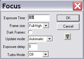
Die Einstellungen sollten wie auf den linken Bild seien. Mit dieser Funktion wird wiederholt eine Aufnahme mit einer gewissen Belichtungszeit (Exposure Time) in diesem Beispiel von 0.5s gemacht. Die Aufnahmen werden automatisch geladen und dargestellt. Nun kann das Teleskop mittels CW3 oder des Handterminals für den Okularauszug fokussiert werden.
Planet Mode

Der Planet Mode folgt den gleichen Prinzipien, die die Subframe-Option bei MaximDL. Aufgerufen wird der Planet Mode indem in dem Auswahlmenü für den Fokus (siehe obige Abbildung) der Menüpunkt Frame size auf Planet Mode gesetzt wird. Ist die Fokusreihe bereits gestartet kann diese über den Pause-Button in dem Statusmenü (siehe Abbildung rechts) unterbrochen werden und der Planetmodus über das Drop-down-Menü (Frame) ausgewählt werden. Über den Resume-Button kann die Fokusreihe anschließend fortgesetzt werden.

Hat man eine Fokusreihe im Planet Mode gestartet, wird zuerst eine Aufnahme in voller Auflösung erstellt und auf dem Bildschirm dargestellt. Auf dieser Aufnahme kann man den Subframe auswählen, welcher anschließend im Rahmen der Fokusreihe ausgelesen und dargestellt wird. Die Größe des Subframe kann über das kleine weiße Rechteck definiert werden. Die Größe dieses Rechtecks lässt sich über die kleinen Kästchens in der oberen linken und unteren rechten Ecke anpassen. Der Subframe sollte so gewählt werden, dass möglichst viele nahe beieinander liegende Punktquellen enthalten sind.
Der Fokus kann jetzt bequem und relativ zügig verbessert werden. Als Anhaltspunkt für die Qualität der aktuellen Fokuseinstellung kann auch die maximale Countzahl (Peak) herangezogen werden, die dem Statuspannel entnommen werden kann. Je besser die Fokussierung desto höher ist die Countzahl. Dabei muss allerdings beachtet werden, dass Schwankungen bis zu einer Größenordnung von 30% in aufeinanderfolgenden Aufnahmen aufgrund des Seeings völlig normal sind.
Die beiden Aufnahmen unten geben Aufschluss über die Verbesserungen, welche bei relativ schlechtem Seeing zu erreichen sind.


Fokusierhilfen
Lochblenden
Lochblenden haben sich in der Astrophotographie als Fokussierhilfen und zum Test der Abbildungsqualität von Teleskopen bewährt. Lochblenden mit zwei Öffnungen bezeichnet man in der Regel als Scheinerblende, wohingegen Lochblenden mit mehr als zwei Öffnungen als Hartmannblende bezeichnet werden. Angebracht werden Lochblenden vor der Öffnung des Teleskops.

Zur Fokussierung wird das Teleskop auf eine helle Lichtquelle (z.B. einen hellen Stern) gerichtet. Da das Licht, welches durch die unterschiedlichen Öffnungen der Lochblende fällt, an verschiedenen Punkten die Ebenen vor und hinter der Fokalebene passieren sind mehrere Abbildungen der Lichtquelle zu erkennen, falls das Teleskop defokussiert ist. Durch anpassen des Fokus können die mehrfachen Abbildungen zum überlappen gebracht und schlussendlich zu einer Punktquelle vereinigt werden. Hat man dies erreicht kann man davon ausgehen, dass man den optimalen Fokus gefunden hat.
Scheinerblende
Für das Praktikum steht bisher eine Scheinerblende mit rechteckigen Öffnungen zur Verfügung, bei der einer diese Öffnungen um 45° gegen die andere gedreht ist (siehe rechte Abbildung). Diese Lochmaske hat den Vorteil, dass aufgrund der Beugung an den Öffnungen die Abbildungen des zu fokussierenden Objektes jeweils mit Spikes überlagert sind, welche entsprechen der Drehung der Öffnungen ebenfalls um 45° gegeneinander verschoben sind. Die Spikes sind eine gute Hilfestellung bei fokussieren, da diese nur bei idealer Fokussierung ein symmetrisches “Sternchen” bilden (siehe Abbildung unten). Eine Vorlage der beschriebene Scheinerblende im A2-Format für das C14 von Celestron ist hier zu finden.

Bathinovblende
Kommt noch!