Focusing
A good focused telescope is essential for each successful observation, especially if deep-sky exposures shall be taken. With a small amount of exercise, an optimal focus can be easily found within a few minutes. The following small manual shall give assistant for this purpose.
General remarks
The telescope is focused via an Electronical Focuser Assembly (EFA), which can be controlled manually or via the OMS. Since the EFA has a limited adjustment range (33mm), different adapters (M68) can be mounted on the EFA, so that the focus can be achieved with different instruments.
Calculation of the ideal adapter
Empirical values with regard to the focus:
| Instrument | Adapter [mm] | Position of the EFA [μm] |
|---|---|---|
| QHY600M | 20+10 | 16900 |
| SFT-8300 | 20+10 | 9500 |
| Canon 700D | 20+10 | 13000 |
| Baches + QHY268M | 10 | 15000 |
| Baches + QHY268M + Barlow | 20 | 17500 |
| DADOS + QHY268M | 0 | 17000 |
| Hyperionokular: 36mm | 80 | 14500 |
| Hyperionokular: 22mm | 80 | |
| Hyperionokular: 13mm | 80 | 25200 |
| Canon + Superzoom | 80 | 19550 |
Manually


A hand-held terminal (figure 1) is available for manual operation of the EFA. The hand-held terminal is located in the movable storage container in the dome. The hand terminal has to be mounted on the black control box labeled Electronic Focusing Accessory on the back of the telescope. The cable of the hand-held terminal needs to be plugged into the port labeled H/C (see figure 2), while the handheld terminal as such should be hung on a silver bolt in the direct vicinity of the control box. Please note that the handheld terminal is only relatively loosely attached to the bolt and therefore there is a risk that the hand terminal could fall off if the telescope is moved a lot. If the hand terminal is mounted, control via the OMS is not possible, therefore the hand terminal is usually not mounted to the telescope.
 Fig. 3: Back of the telescope with mounted hand terminal
With the buttons In and Out of the hand terminal, the EFA can be moved in and out. The remaining buttons are for a derotator, which our telescope does not need. Therefore, these buttons are without function.
Observatory Management System (OMS)
The focusing by means of the OMS is done by the program PWI3, which besides focusing also controls the fans and the heaters installed in the telescope. The last two points are described in more detail in the article temperature regulation.

The operation of the EFA is basically self-explanatory. The current position can be found in the field Focus Status, while the EFA can be moved via the buttons IN and OUT. From a drop-down menu, one can select Fast, Slow and Increment for the speed. Using the GOTO menu, the EFA can be moved to a specific position. An ongoing movement can be stopped at any time using the STOP button. The temporal course of the temperature of the main mirror, the support of the main mirror, the secondary mirror and the ambient temperature can be shown and hidden using the buttons SHOW and HIDE, respectively.

Auto Focus
PWI3 also offers the possibility of automatic focusing. For this purpose, PWI3 connects to MaximDL to take the necessary pictures. Hence, before starting the automatic focusing, the camera must be connected to MaximDL. With a click on AF CONFIG the settings can be adjusted. One of the most important settings is the Step Size (micron), which defines the step size in micrometers that the EFA should move at each focusing step. Steps (Image Count) is the number of focusing steps performed by the EFA and the number of images to be captured. The exposure time in seconds must be specified at Exposure length (sec). So far the following settings have proven to be useful:
  Step Size (micron)    = 150
  Steps (Image Count)   = 17
  Exposure length (sec) = must be chosen depending on the object

After starting the auto focus, PWI3 will perform the individual focusing steps, move the EFA by the Step Size and take one image at a time. Afterwards, PWI3 will start the program PlateSolve (see above), which will analyze each image, search for stars, determine the diameter of these stars and estimate the focus. This is then listed in a table. With a click on Show Graph you can visualize the result. The determined star diameter is displayed over the position of the eyepiece extension. In the ideal case this representation follows a V-curve, which is also fitted into the data.
In the following we show an example of a successful and an unsuccessful auto focus run:
Successful auto focus:


Unsuccessful auto focus:


There are several reasons why a autofocus run can fail. One of them is that the ideal focus is not in the area that is covered by the autofocus run. It is therefore recommended to focus the telescope roughly by hand before. Furthermore, it can be that no star is found and therefore the quality of the focus cannot be estimated. A reason for this may in turn be that the option Use a Subframe, Central 1/4 pixels was selected during setup and that there is no star in the central area of the chip.
Using MaximDL
All our SBIG-CCD cameras can be controlled via CCDOPS as well as MaximDL. Here we will first concentrate on MaximDL before we deal with CCDOPS below. The most important functions of MaximDL have already been introduced in the main article on MaximDL.
The best way to focus is to use the Exposure Preset Focus, which can be selected via the corresponding drop-down menu in the Exposure Tab of the Camera Control window (see below). In this preset many settings, important for focusing, are already pre-selected. In the examples shown below the exposure time (Seconds) is set to one second, this must be adjusted according to the object used for focusing.

After a click on Start images are continuously taken and displayed. Now the telescope can be focused by means of CW3 or the hand terminal of the EFA. To find the coarse focus, it is recommended to first approach a bright star and to focus in such a way that the diffraction ring disappears. Rough values for the focus with the different instruments and eyepieces can be found in the table above.
In order to further optimize the focus, a globular cluster can be observed. The low angular distance between the stars in a globular cluster facilitates very good focusing results, since the Airy discs of the individual stars can only be separated with a very well focused telescope. An optimally focused telescope operates with a seeing limited resolution, which for our site is often larger than 2“. This is significantly worse than the diffraction limited resolution of our telescope, which is 0.23″. The Rayleigh criterion describes the theoretical limit at which two Airy discs can be recognized as separated light sources.
The lower 3 panels of the Camera Control window can display various information about the connected cameras as well as statistical information about the images. To switch between the different display modes, you can simply right-click in one of these panels. The right and middle panels are reserved for the cameras, while the left panel can display graphics that show qualitative information about the focus. If no guiding camera is used, the following settings are recommended: left: 3D Profile or FWHM/time, middle: Camera 1 Info and right: Camera 1 Stats.

The information from the left and right panel is derived from the brightest star in the field of view. The 3D Profile is a 3D view of the image of this star, with the intensity being the third axis. FWHM/time shows the Full-width Half Maximum (FWHM) of this star as a function of time. The right panel shows the following information: the position of the brightest pixel in X and Y direction, the value of this pixel, the FWHM of the brightest star, the Half Flux Diameter (HFD) of this star, and the Signal to Noise Ratio (SNR).
As an indication of a good focus, the value of the brightest pixel, the FWHM, the HFD and the SNR can be used. The higher the value in the brightest pixel, the better the SNR, the smaller the FWHM and HFD, the better the focus. It is therefore important to optimize these values during the focusing process. In this respect, the different graphics in the lower left panel can be very helpful, since those illustrate the temporal course.
The middle panel again summarizes the current information about the camera, e.g. if a image acquisition is currently running, which exposure time is set, the selected filter, if the cooling is running and if so, the current and target temperature of the sensor.
Subframes
Subframes offer the possibility to significantly speed up the process of finding the optimal settings for the focus. By reading out only a small area of the CCD, which can be selected by the user, the readout time and also the download time can be greatly reduced.
The subframe mode can be activated by clicking on On in the Subframe section. Now the area to be read out can either be entered directly or defined by mouse. For the former you have to click on the line with X: Y: W: H:. In the window that opens, you can then specify the X and Y values of the start pixel, as well as the width and height of the box to be read. If the option Mouse is activated, a box can also be dragged directly around a star or a group of stars with the mouse. Of course you have to take a picture first  The box can also be moved by clicking on the border and resized by clicking on the corners. Attention: If the focus series is already running, it must be stopped and restarted for the subframe mode to take effect.


ToDO: replace images!
Ussing CCDOPS
In this section, we will only go into the technical details that distinguish the focus using CCDOPS from the focus using MaximDL. The basic functions of CCDOPS were already introduced in the main article about CCDOPS.
To focus the respective CCD camera, use the Focus function in the Camera menu.
Camera -> Focus
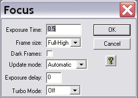
The settings should be similar to the example shown on the image above. In this operation mode, the camera will repeatedly take images of a certain Exposure Time (0.5s in the example above). The individual exposures will be automatically downloaded and displayed. Now the telescope can be focused using CW3 or the hand terminal for the EFA.
Planet Mode

The Planet Mode follows the same principles as the subframe option of MaximDL. The planet mode can be activated by choosing the Planet Mode option from the drop down menu Frame size in the focus menu (see figure above). If the focus series is already running, the plate mode can be activated by pausing the exposures with a click on the Pause button in the status window (see right figure) and choosing the planet mode from the drop-down menu (Frame). Afterwards click on the Resume button to continue the focus series.

The first exposure of a focus series in planet mode will be a full frame exposure. On this full frame exposure, one can select a subframe that subsequently will be readout and displayed within the scope of the focus series. The subframe is defined by the small white box. The size of this box can be adjusted by means of the (very) small rectangles in the upper left and lower right corner of the box. The subframe should be selected so that as many point sources as possible are contained close together.
The focus can then be easily and relative fast adjusted. An indicator for the quality of the focus is also the maximal count number (Peak) that can be found in the status panel. The better the focus is, the higher is the maximal count number. However, be aware of the fact that fluctuations of up to 30% in successive exposures are completely normal due to the seeing.
The two images below show the improvements that can be achieved with poor seeing conditions:


Focusing aids
Aperture masks
Aperture masks have proven their worth in astrophotography as focusing aids and for testing the imaging quality of telescopes. Aperture masks with two apertures are usually called Scheiner apertures, whereas aperture masks with more than two apertures are called Hartmann apertures. Aperture masks are attached in front of the telescope's aperture.

For finding the focus, the telescope needs to be pointed to a bright light source (e.g. a bright star). Since the light that passes through the different apertures of the pinhole passes the planes in front and behind the focal plane at different points, several images of the light source can be seen if the telescope is defocused. By adjusting the focus, the multiple images can be overlapped and finally merged into one point source. Once this has been achieved, one can assume that the optimal focus has been found.
Scheiner mask
For our telescope, we have a Scheiner mask with rectangular apertures, where the apertures are rotated by 45° against each other (see the right figure). The advantage of this kind of Scheiner masks is that the images of the object are superimposed with spikes, due to diffraction at the apertures. These spikes are shifted by 45° against each other corresponding to the rotation of the apertures. The spikes are a good aid for focusing, since the spikes form a symmetric “starlet” only for a well focused telescope. A template of the described Scheiner diaphragm (A2 format) for the C14 from Celestron can be found here.

Bathinov masks
Comming soon!