Table of Contents
OST 2.0 operation
Security remarks
- NEVER look at the Sun with a telescope without a proper sun filter. This can lead to irreparable damage of your eyes and the optical instruments! The OST is not designed for observations of the Sun, so never point it to the Sun!
- WATCH THE CABLES! The user-friendliness of the telescope is based on a high automation of the components, which implies the need of some cables. To avoid getting caught in the cables connecting the telescope and the applied instruments, pay attention to them especially during rotations of the telescope.
- Always close the door to the roof because the hatch of the dome could collide with it, which could damaged both.
General remarks
The observatory can operated complete remotely or semi remotely (being locally in the observatory, using some of the remote capabilities). The handling of the individual components of the observatory is briefly explained in the following, starting with the manual controls before the remote capabilities are discussed.
The dome and the roof
Information on the dome and the roof can be found in a separate article.
Manual operation
Switch on the observatory
- remove the covers (if any) of the telescope's main and secondary mirrors and place them on the movable storage container or one of the desks
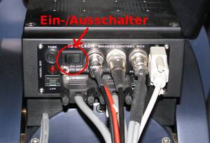
- press the On / Off button at the telescope's mounting and wait until the booting process is completed
Open the dome
- use the dome remote control to first open the shutter
- as needed, open the horizontal hatch
The Mount: GM4000 HPS II
A description of the hand terminal, including some aspects of the operating system are described in a separated article.
Setting the time
For the correct calculation of the object positions, the telescope needs to know the current time. As the internal clock is often ahead of the actual time, it needs to be corrected before each observation.
To set the date and time, use the hand terminal:
MENU - Local Data - Clock - Date and Time
In the following screen one can set the time (accurate to the whole seconds) with the numeric keys. It is useful to have a radio clock available or to use an Internet service, such as this one. Set a time approximately 30 seconds ahead of the current time and wait until the time set on the hand terminal is reached, then press ENTER to confirm.
Remote operation
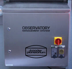
The remote capabilities of the observatory are provided by the Observatory Management System (OMS), which is the large metallic box right above the left desk in the dome. The in- and outdoor webcams, the all-sky monitor, as well as the temperature regulations and ventilation system of the mirrors can only be operated by means of the OMS.
Log in
The OMS is accessed using the Remote Desktop Protocol (RDP). However, login is restricted to the local IP address space. Therefore, you must first log in to one of the Linux machines of the astrophysics groups or establish an SSH tunnel to these machines. The columba evaluation computer can be used for the lab course. A how-to explaining the SSH login is available.
To use RDP from a Linux machine, we recommend Remmina, which is available on all our Linux installations. A sample configuration for Remmina is described in this article. This article also explains how to login from a Windows machine.
Startup
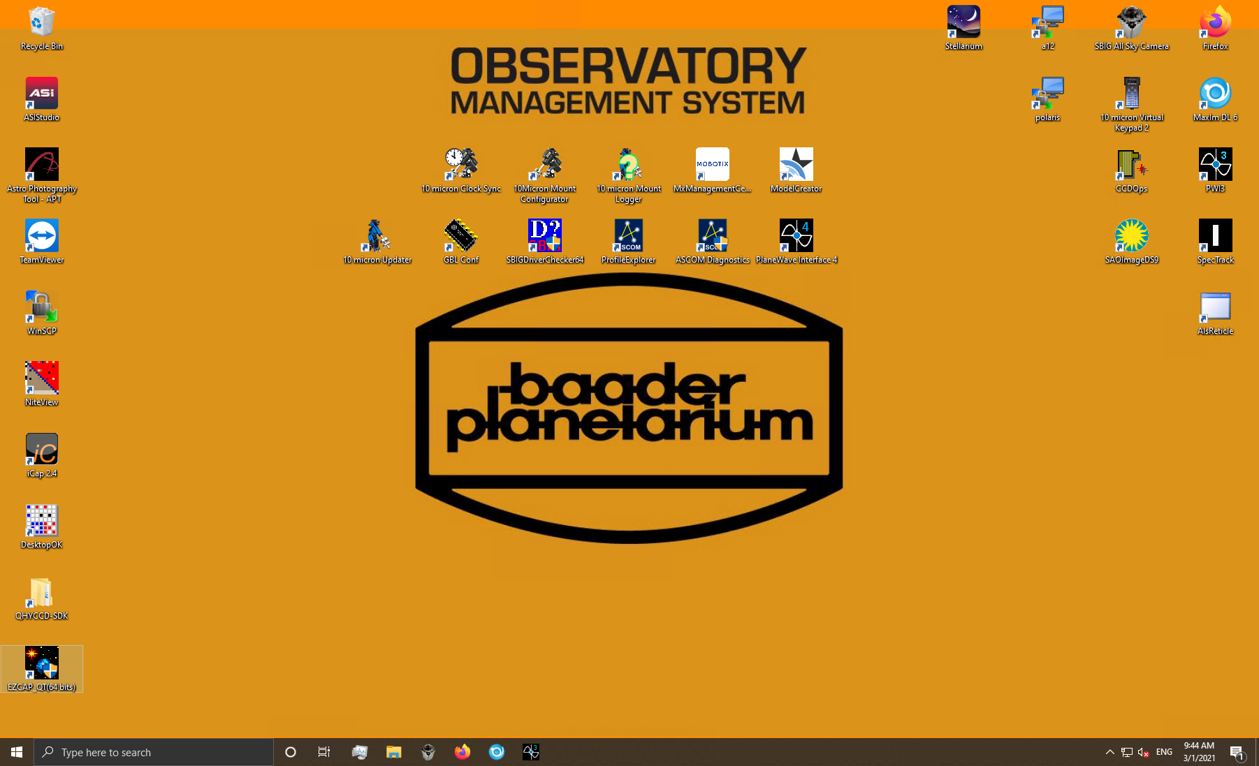
After logging in to the OMS you will see the following desktop. If the icons are not so nicely arranged, the configuration shown, to which we will refer here in part, can be restored using the program DesktopOK.
The most important programs are grouped in the upper right corner of the desktop, while the programs that are not used so often are arranged on the left side. The programs in the middle of the desktop are usually not relevant for normal operation. The very most important programs are also placed in the taskbar.
Powering up and booting devices
The first thing to do is to start Firefox. Some important devices of the observatory bring their own web interface and can be accessed through web browser. Firefox can be started by clicking on the icon in the upper right corner of the desktop or alternatively from the taskbar. The start page shows the OMS control menu (see below).
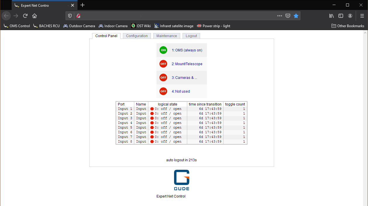
As shown in the figure above, four devices can be switched using the control menu. In position 1 is the OMS itself, which of course may never be switched off and is therefore always highlighted in green. On position 2 is the telescope or the mount. The 3rd position is used to switch the cameras, the all-sky camera and all other electrical attachments to the telescope. The 4th position is currently not occupied by a device.
If you click on Cameras &… the buttons for switching on and off become visible. By clicking on On, the cameras and all other telescope attachments can be switched on. The corresponding entry is then colored green. After the observation and after you have shut down the cameras properly, you have to switch off the power supply of the cameras and all attachments again by clicking Off.
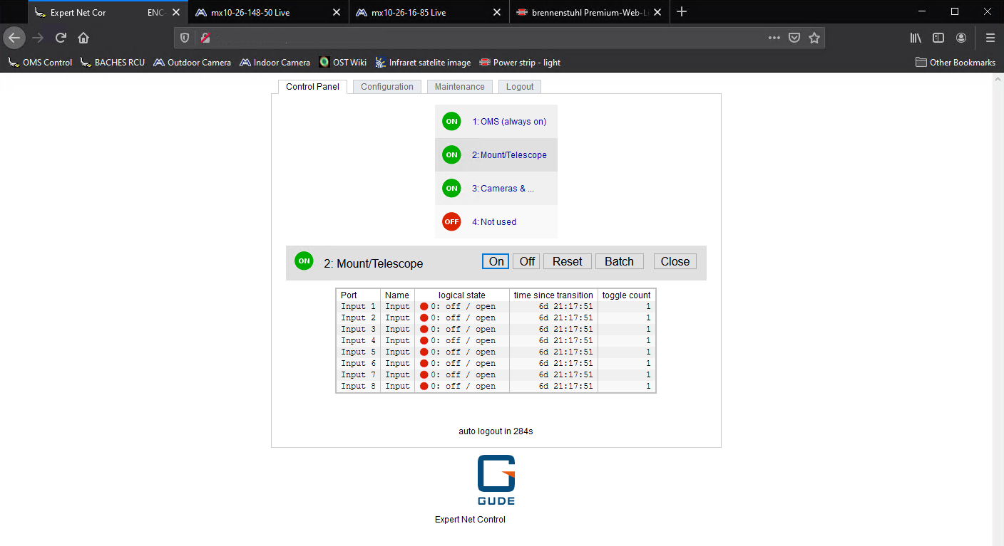
For telescopes/mount the procedure is slightly different. Click on the Batch button and then make sure that the settings are as follows: switch on, wait 3 sec(s), switch off. Then click on Ok. The status indicator will briefly go to green and then change back to red. This is perfectly normal and expected. More about this below in the section After the observations. After about 20 seconds, the mount should be fully booted and ready for operation.
Get an overview
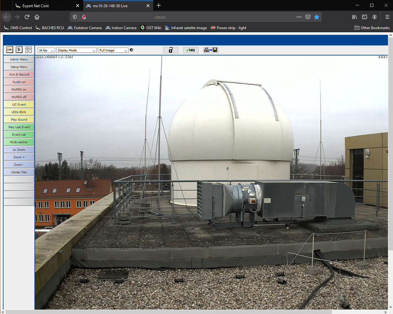
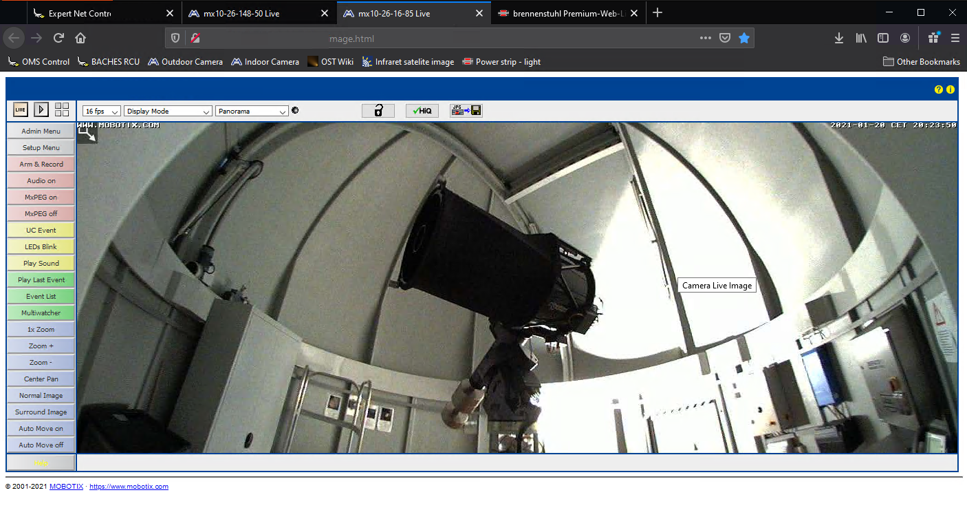
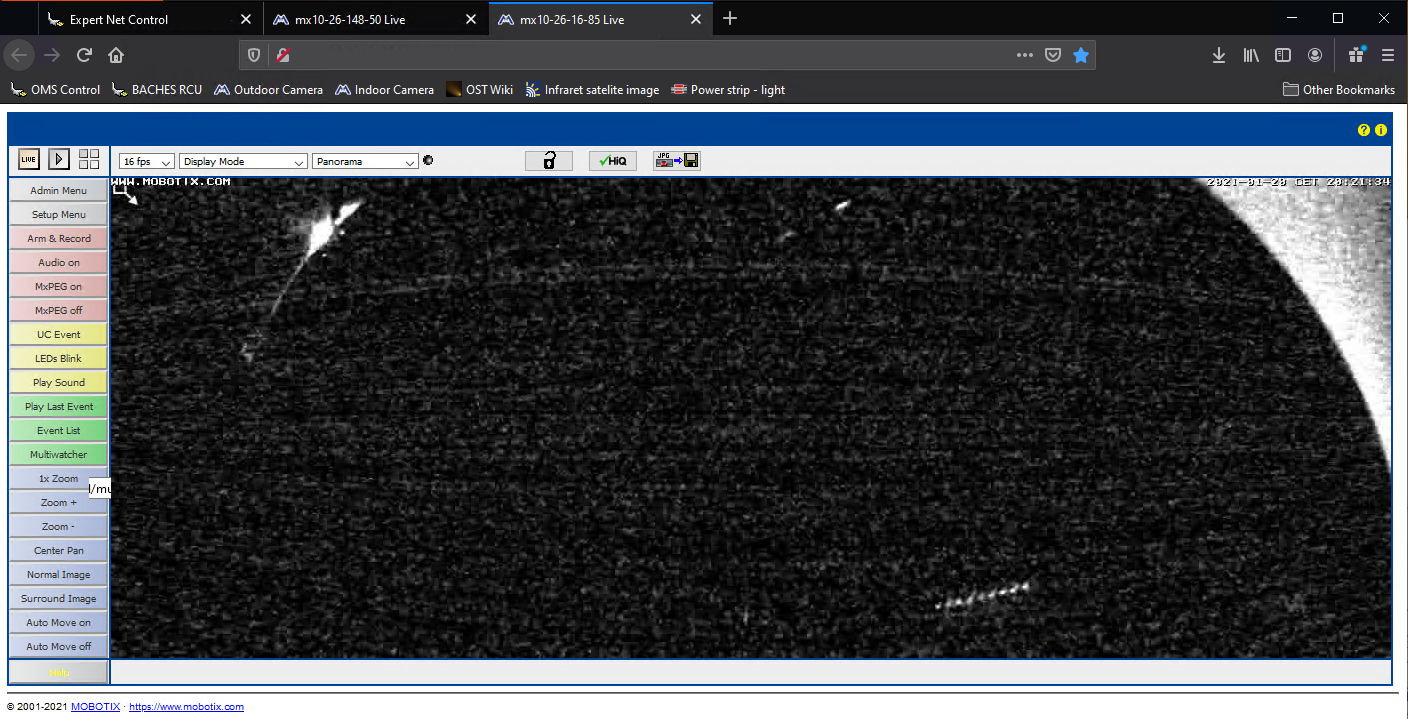
It is a good idea to take a look at the surveillance cameras. We have an indoor and an outdoor camera. These are likewise accessible over Firefox. To do this, click on Outdoor Camera or Indoor Camera in the bookmark toolbar at the top.
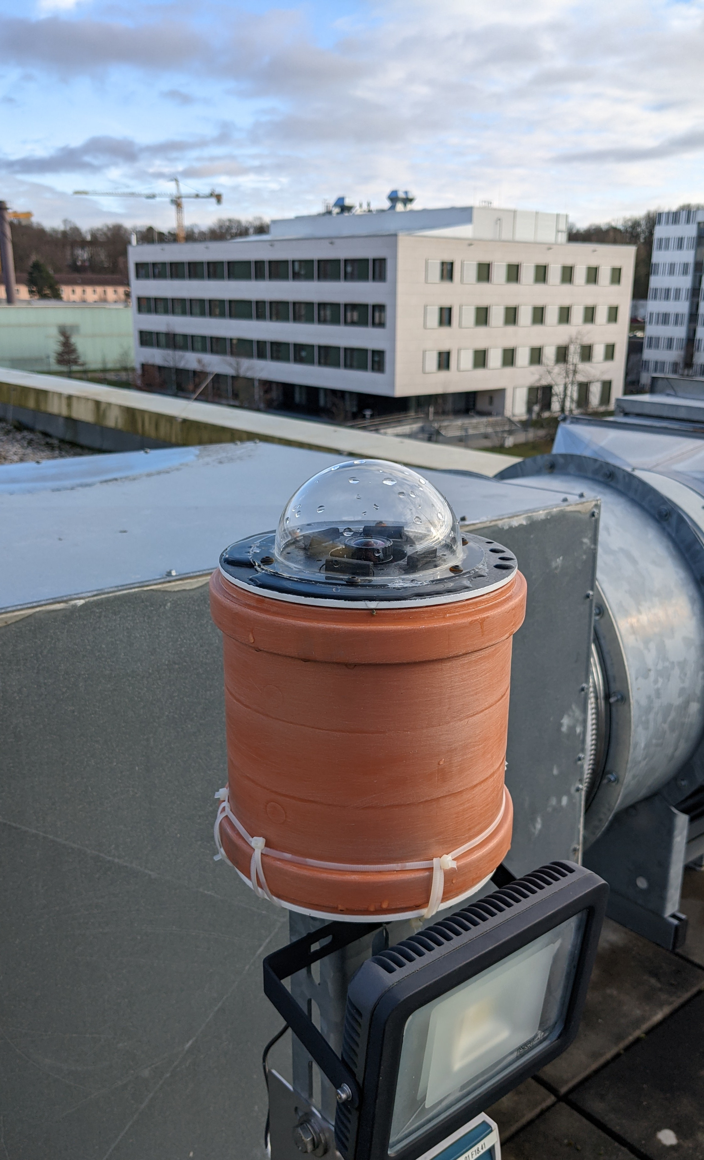
The outdoor camera is located on a pole a few meters away from the dome. On this pole is also the all-sky camera, which we will go into in more detail in a moment. You won't see much on the inside camera at first, since the dome is still closed and normally no light is turned on inside the dome 
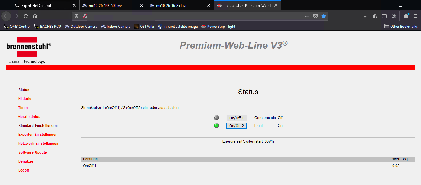
If you still want to get an overview of the inside of the dome, we also have the possibility to turn on the light in the dome via the web browser. To do this, click on Power strip - light in the bookmark bar at the top. On the page that opens, you have the possibility to turn on the light as well as to switch the power strip at the bottom of the telescope's pillar. In this way it is also possible to operate cameras that do not have a plug that fits into the OMS control hub, which is located on the telescope and which is switched via the OMS control window in the web browser (see above). To turn the power strip and light on and off simply click On/Off 1 and On/Off 2, respectively. Below is the interior view again this time with the light on.
MaxIm DL
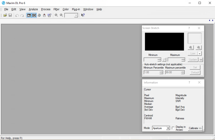
MaxIm DL is the core element in the control of the observatory. The dome, the mount, or telescope and all cameras can be controlled via this software. For details on MaxIm DL and how to connect it to the observatory components, please refer to the MaxIm DL article.
Opening the dome
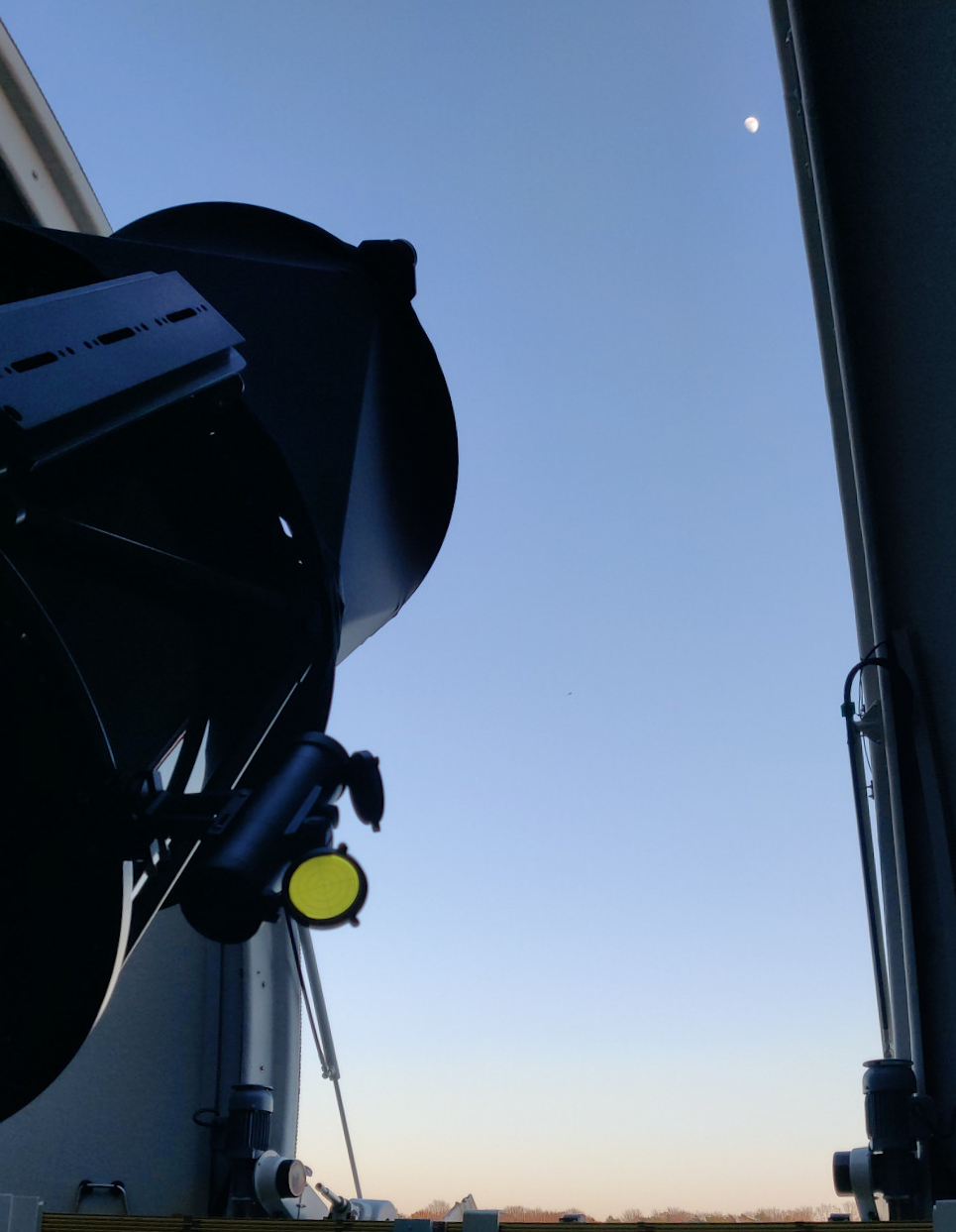
The dome can be opened either by hand control or by MaxIm DL. For the latter, just click on the Open button in the Dome tab of the Observatory control window of MaxIm DL and both the hatch and the shutter will open fully automatically.
Ready for operation
If you have done all these steps successfully, the observatory is basically ready for operation. In the following we will discuss which devices and software are still to be discovered and what else can be done 
The All-Sky Monitor
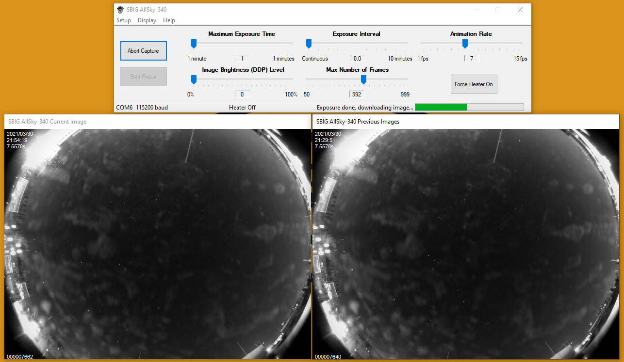
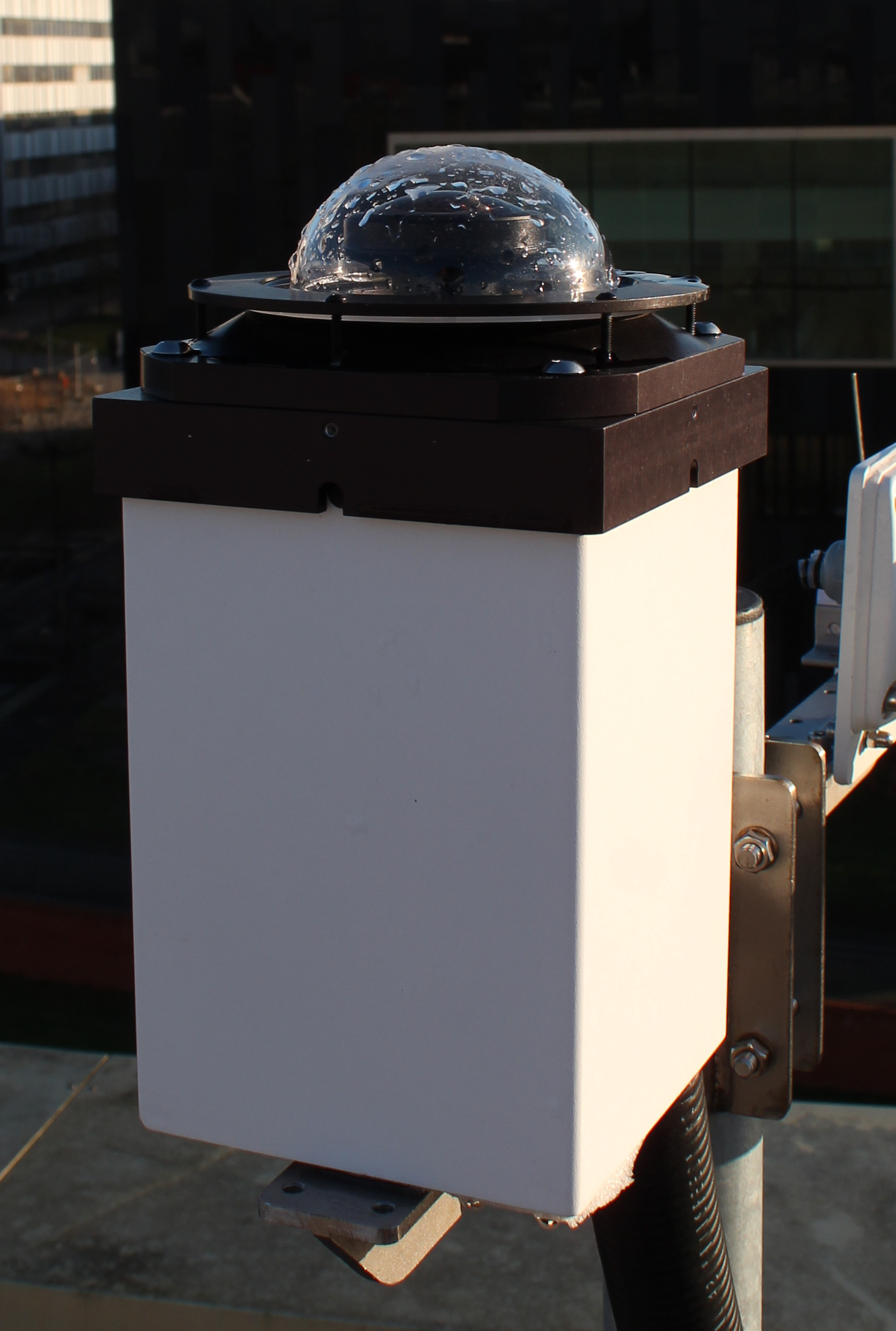
The All-Sky camera (see photo) from SBIG offers the possibility to get a good impression of the given observing conditions. As soon as the power supply for the cameras is switched on, the software for controlling the all-sky camera (see figure below) can be started. The corresponding shortcut on the desktop is called SBIG All Sky Camera.
The All-Sky monitor is already focused and it is usually not necessary to adjust the default setting, so you can click Start Capture directly. The camera will start capturing images continuously. The current image is displayed in the SBIG ALLSky-340 Current Image window (on the left of the image above), while the SBIG ALLSky-340 Previous Images window (on the right of the image above) shows a video from the images already captured. The camera adjusts the exposure time automatically. Especially in darkness, you may have to wait a few exposures until the camera has adjusted the exposure time correctly and you can then see the surroundings and the night sky. The camera is connected to the OMS via a serial connection, which makes the connection stable but also very slow, so that it takes a while until the individual images are downloaded.
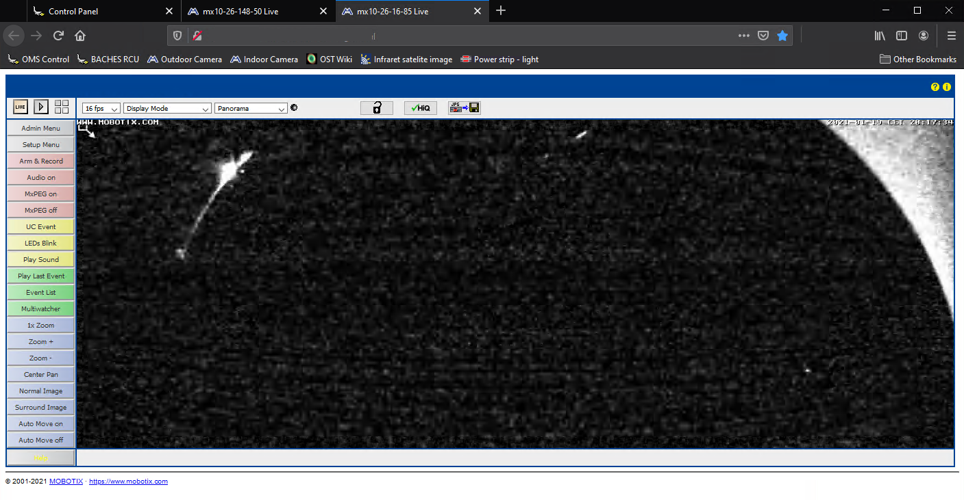
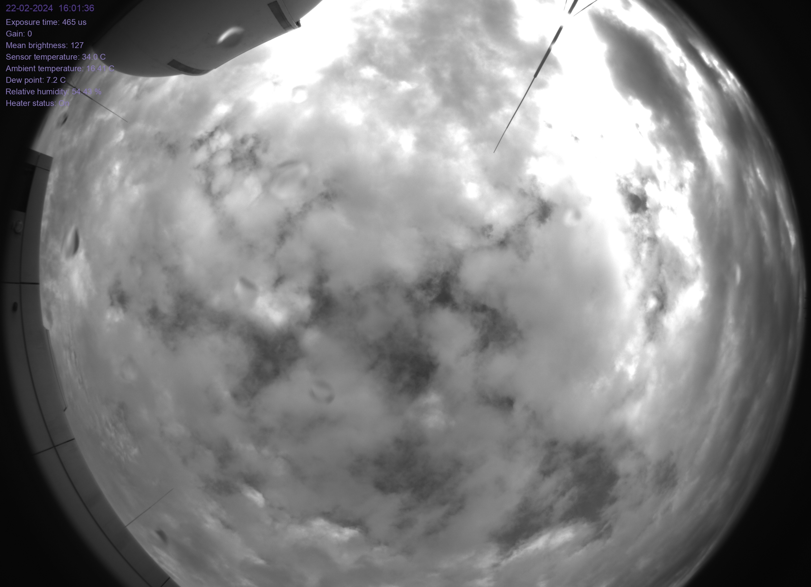
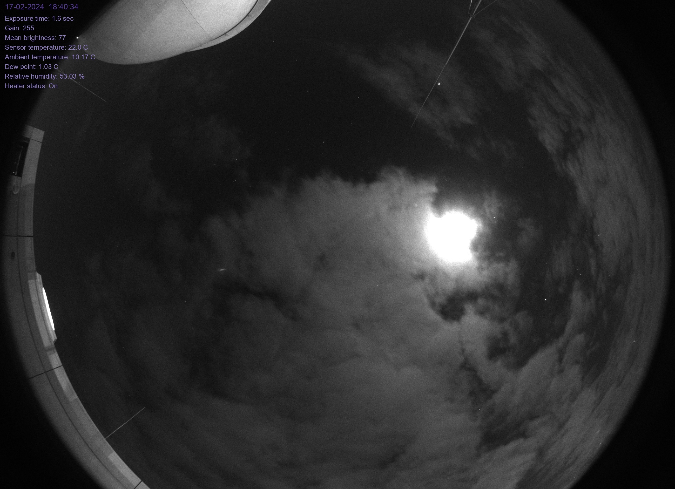
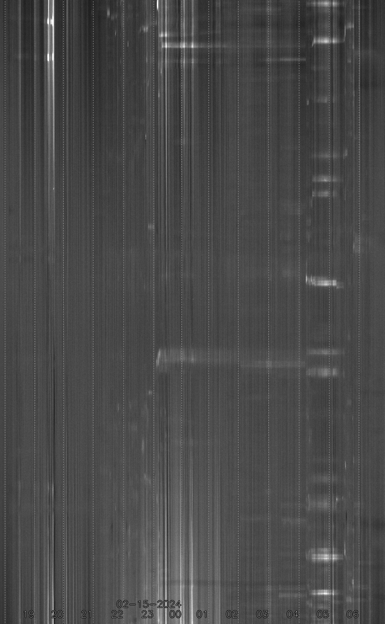
In addition to this well-established all-sky camera, we now have our own construction that is in operation 24 hours a day and provides a Live-View that is accessible to all. In addition a Video, a keogram and a star trail exposure have been made for each night of the last weeks.
Focusing & PWI3
How to focus the telescope and what the software PWI3 has to do with it is described in the following article.
Observations
Observations with the eyepiece
There are eyepieces with different focal lengths. Start with an eyepiece of the largest focal length, then focus and use the direction buttons
N - S - E - W
to move the object to the center of the field of view. Afterwards replace the eyepiece with one of lower focal length and refocus the telescope. After observing, remove the eyepiece and reattach one of the spectrographs or cameras with the appropriate adapter.
Observations with a camera
Observations with the spectrographs
Changing the instruments
There are two basic things to keep in mind when changing instruments: First, the focuser has a limited range of adjustment, which means that different adapters (M68 thread) are needed for different instruments. In the focusing article, we explain in more detail how to calculate the ideal adapter length and list the adapter lengths normally used for the most common instruments.
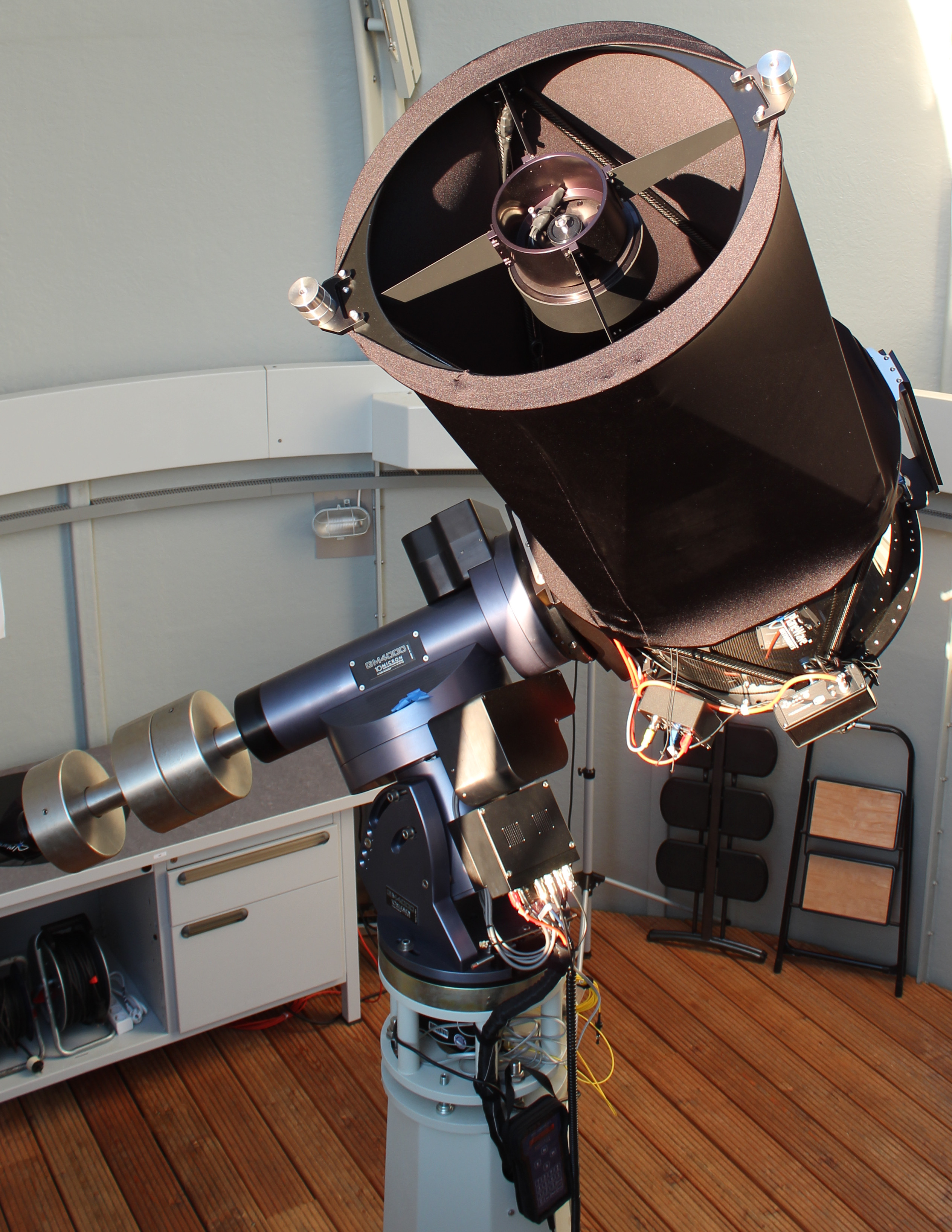
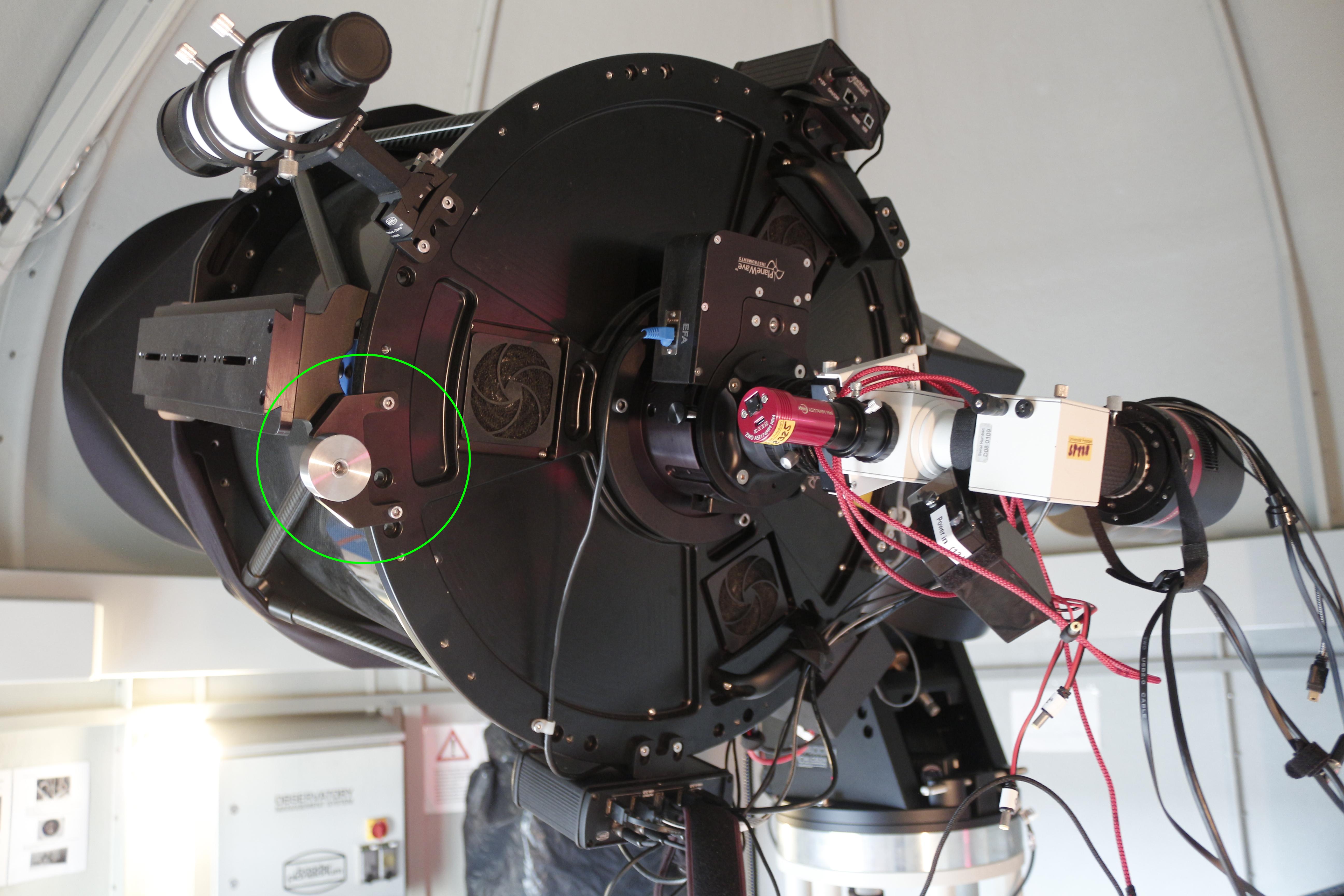
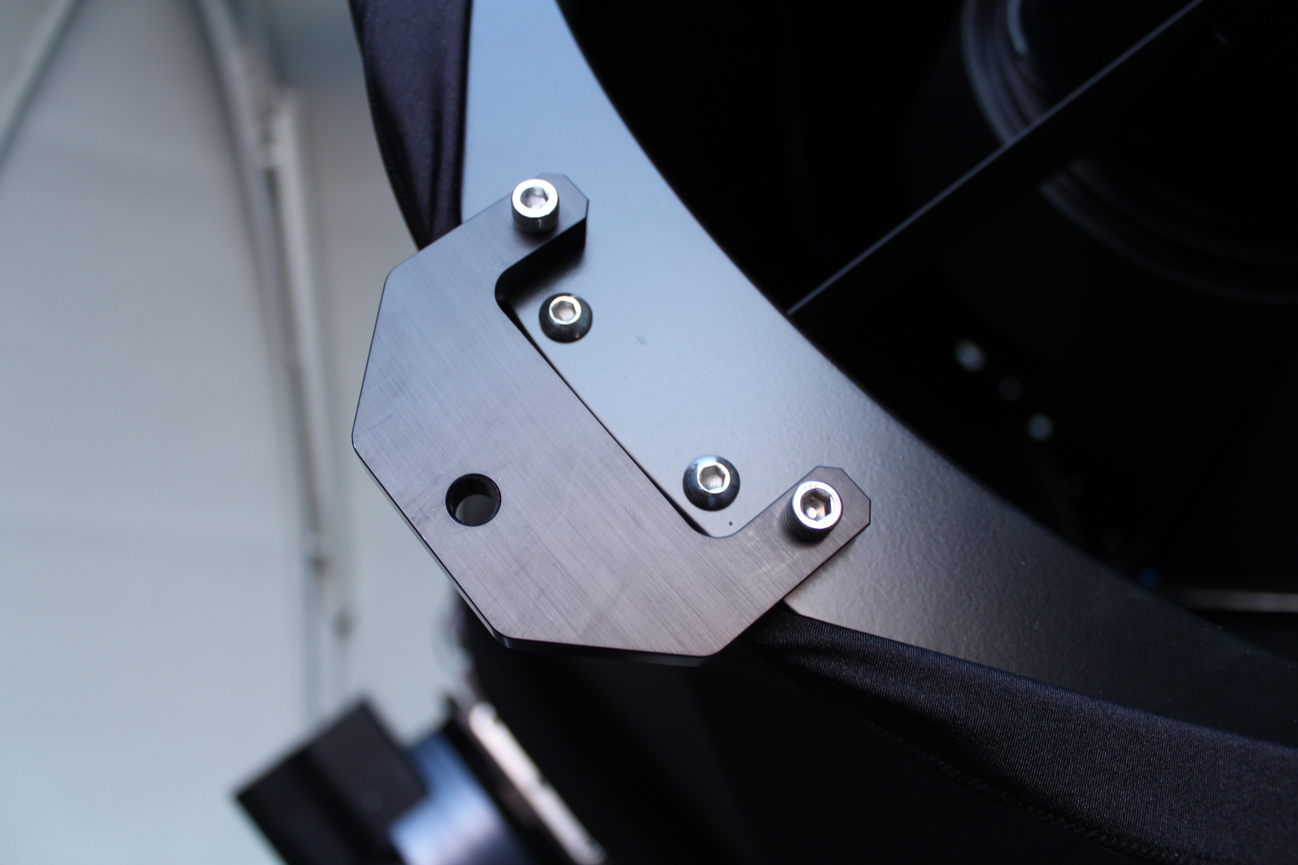
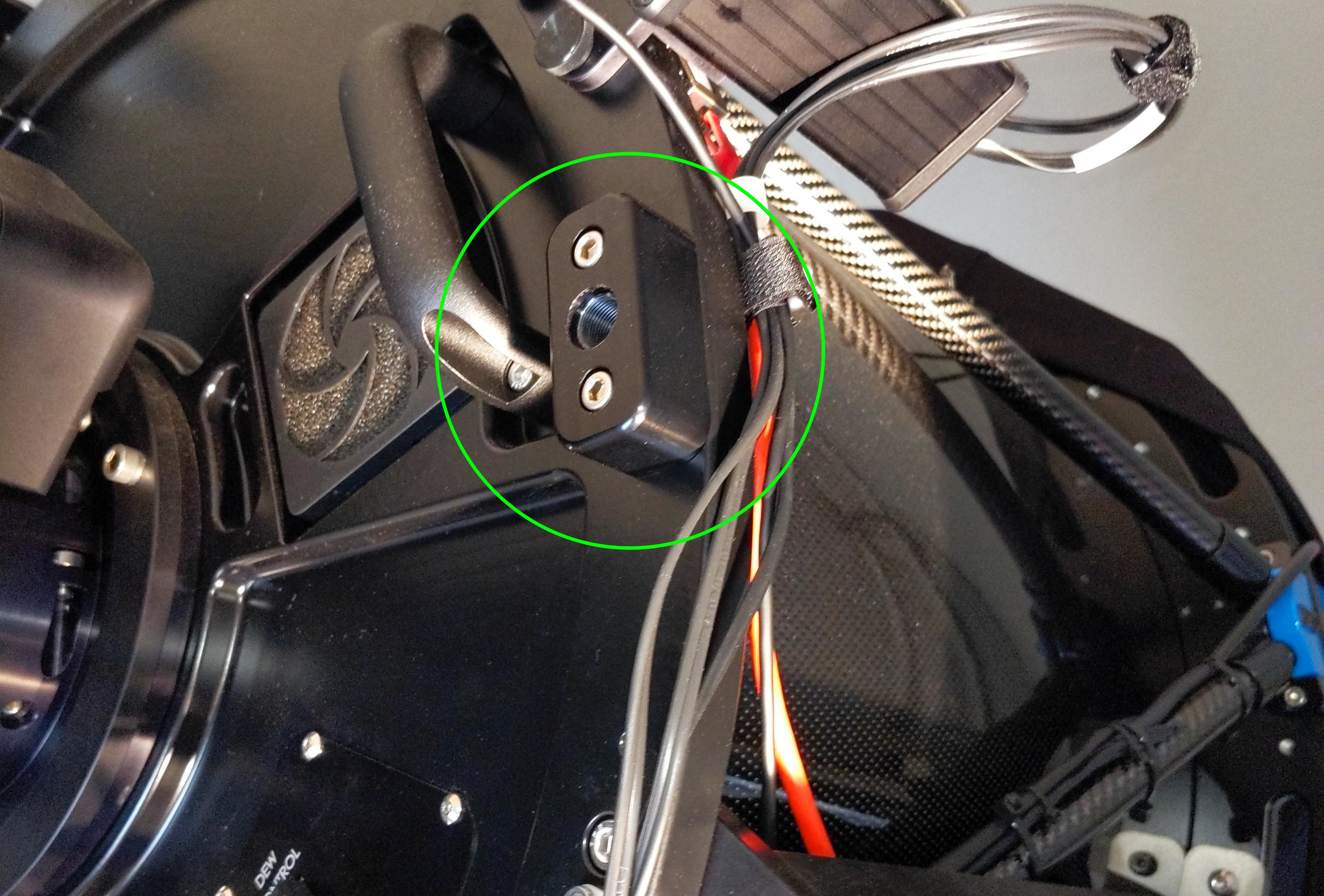
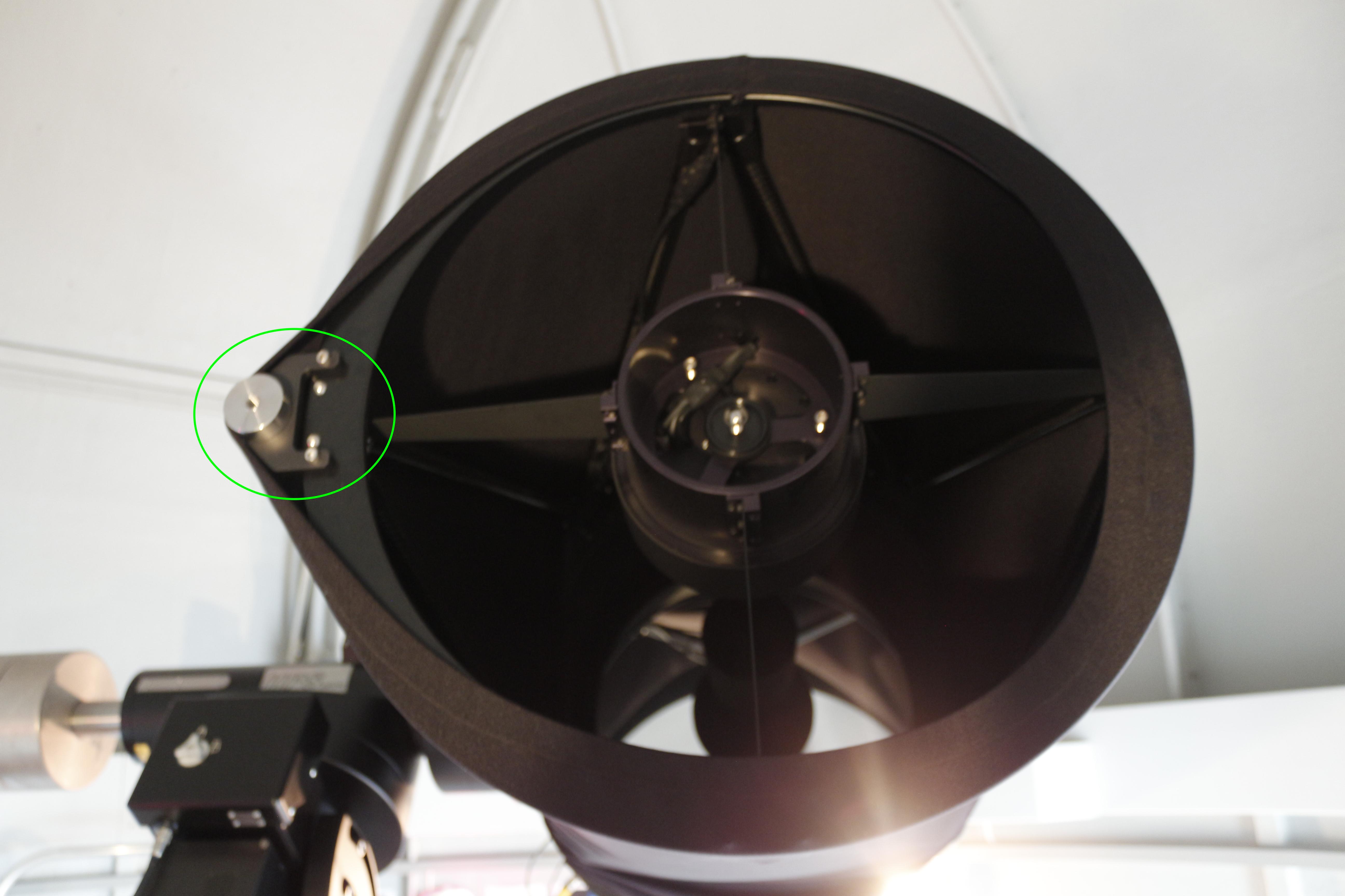
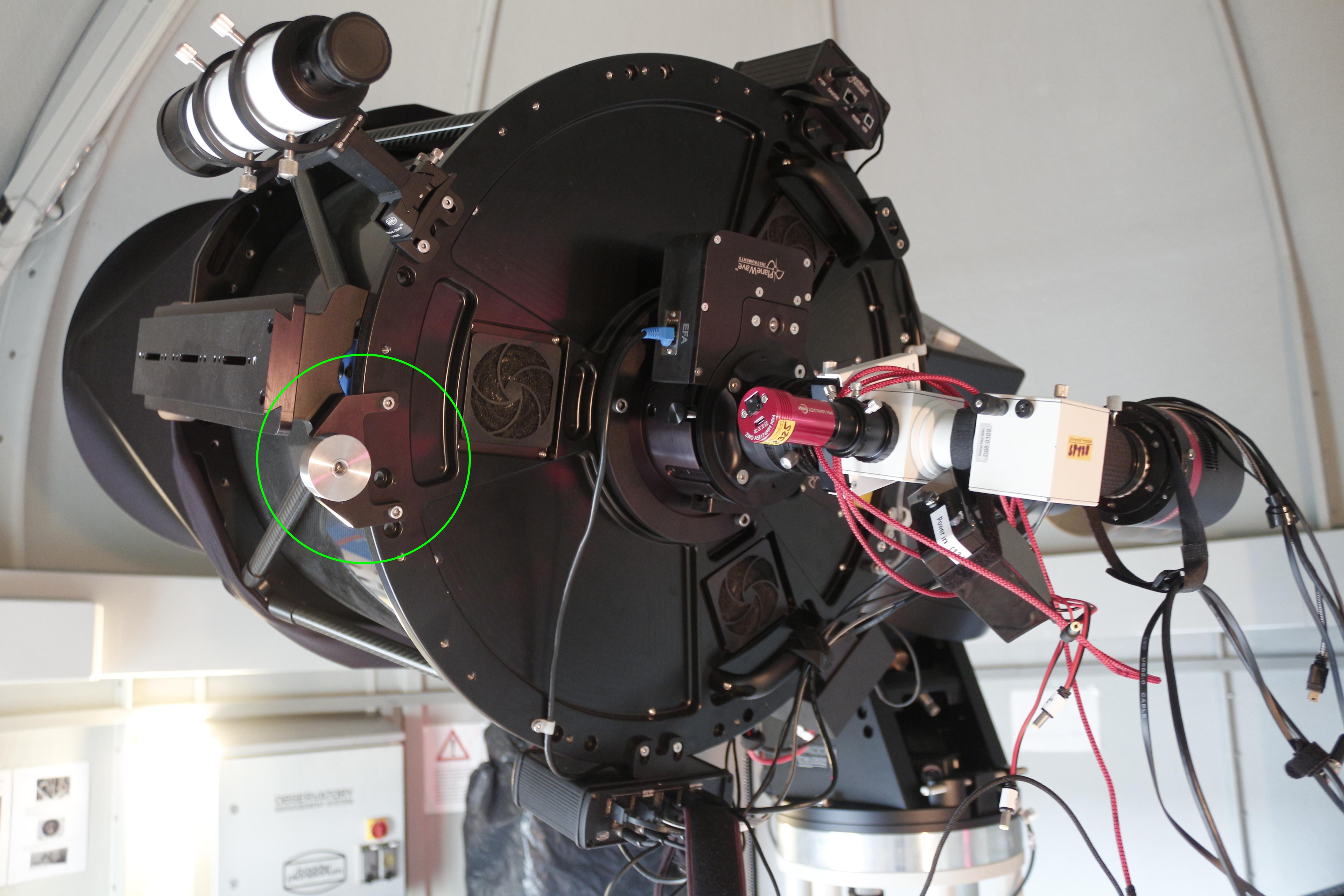
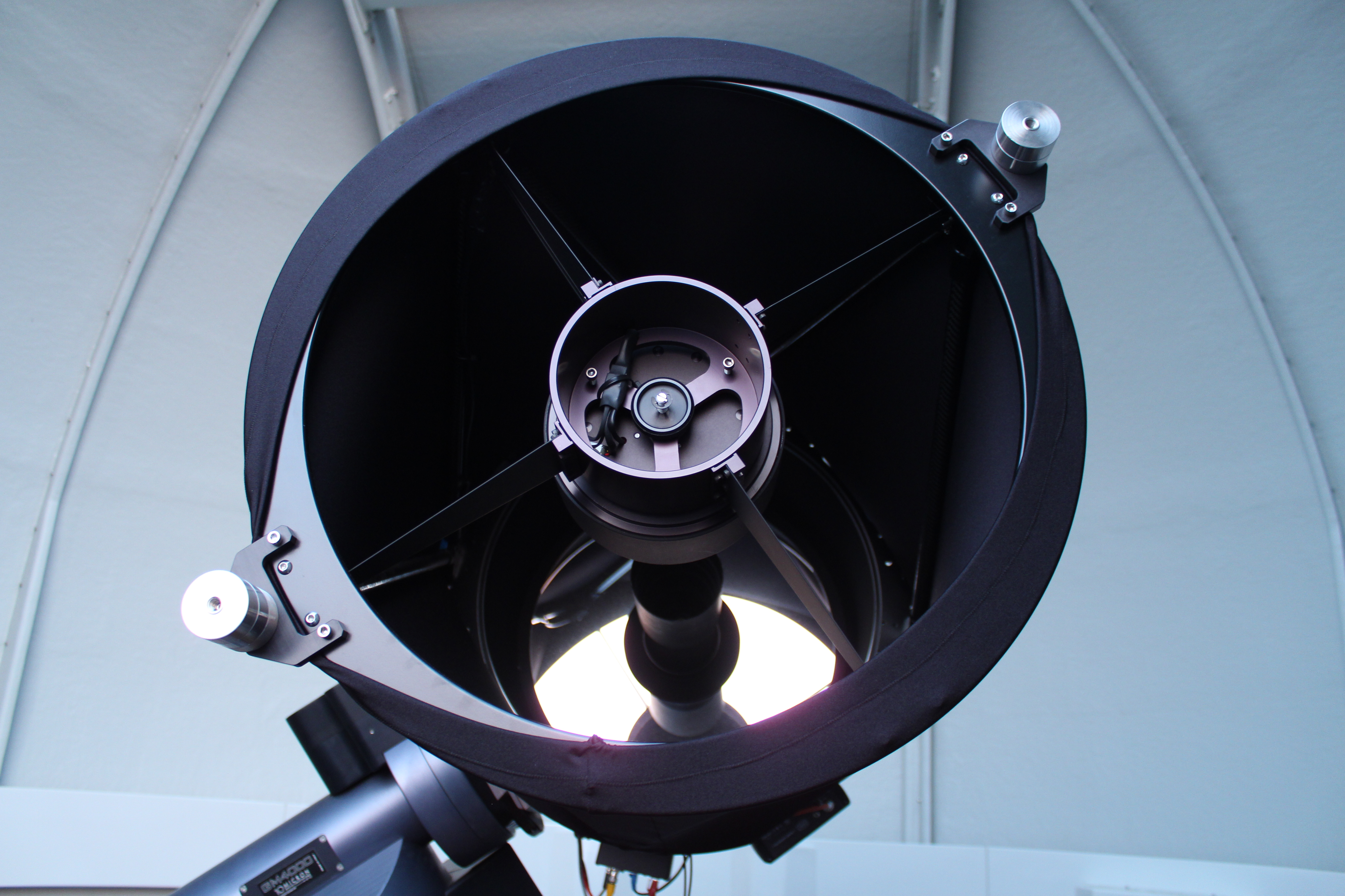
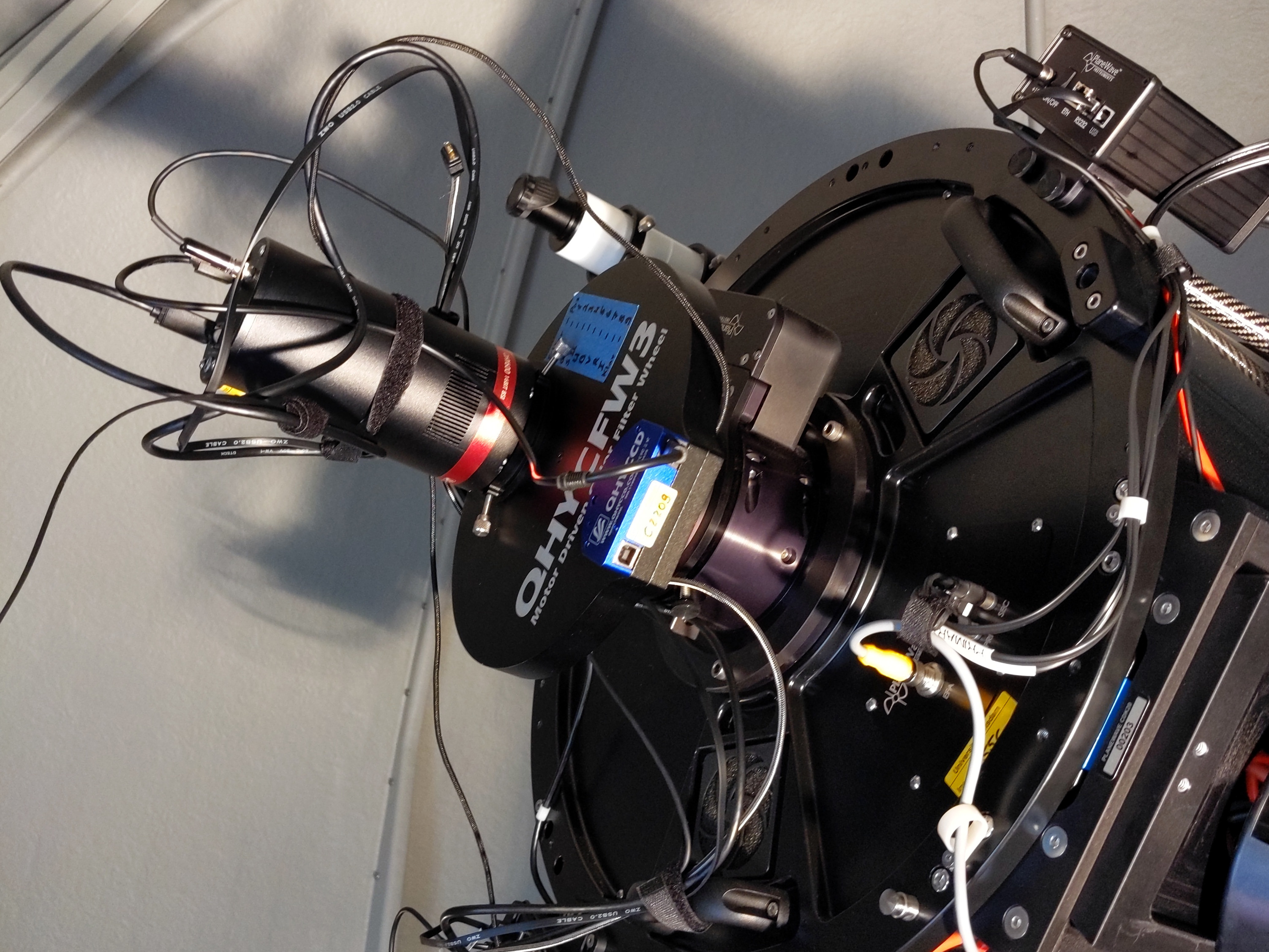
In addition, the interchangeable balancing counterweights on the tube should be matched to the instrument (see table below). Several small 230g counterweights and a two 1kg counterweights are available. The latter are mounted on a rod on which they can be moved as required. The rod holder remains attached to the tube at all times.
The counterweights are located in the large metal cabinet. The small counterweights are screwed onto a counterweight holder, which usually has to be mounted first. When handling the counterweights at the front of the tube, the telescope should be positioned as close to the ground as possible to prevent the counterweights from falling into the tube when they are screwed on or off.
Configurations:
After the observations
Parking & warming up
After the observation, the telescope must be returned to its original configuration. For this the following things have to be done:
- Switch off camera cooling (if applicable): First you should switch off the cooling of the cameras or shut them down. To do this, click Warm Up in the Setup tab of the Camera Control window of MaxIm DL.
- Close Dome: Then you should close the shutter and the hatch of the dome. To do this, the dome can be closed manually using the manual control, making sure that the flap is closed first and then the gate. Alternatively, you can close everything together with one click in MaxIm DL. To do this, click Close in the Dome tab of the Observatory control window and then make sure that the Slave Dome To Scope option is re-enabled.
- Park Telescope/Mount: The next step is to park the mount and with it the telescope. This can be done via the hand control or again via MaxIm DL. For the latter you have to click Park in the Telescope tab of the Observatory control window.
Shutdown
Once the telescope is parked, the cameras are warmed up to ambient temperature, and the dome is closed, the shutdown of the observatory can be started. The following steps are necessary:
- Disconnect MaxIm DL:
- Cameras: Again, simply click on Disconnect in the Setup tab of the Camera Control window.
- Dome, Mount/Telescope & Focuser: In the Setup tab of the Observatory control window, click on the Disconnect buttons of the respective devices or click Disconnect All right away.
- Close MaxIm DL
- Close PWI3
- Shutdown the All-Sky-Monitor: First stop the image series by clicking Stop Capture in the SBIG AllSky-340 software, wait until the last image has been downloaded and then close this software as well.
- When the cameras are back to ambient temperature, click Off next to Cameras &… in the OMS control panel tab of the web browser.
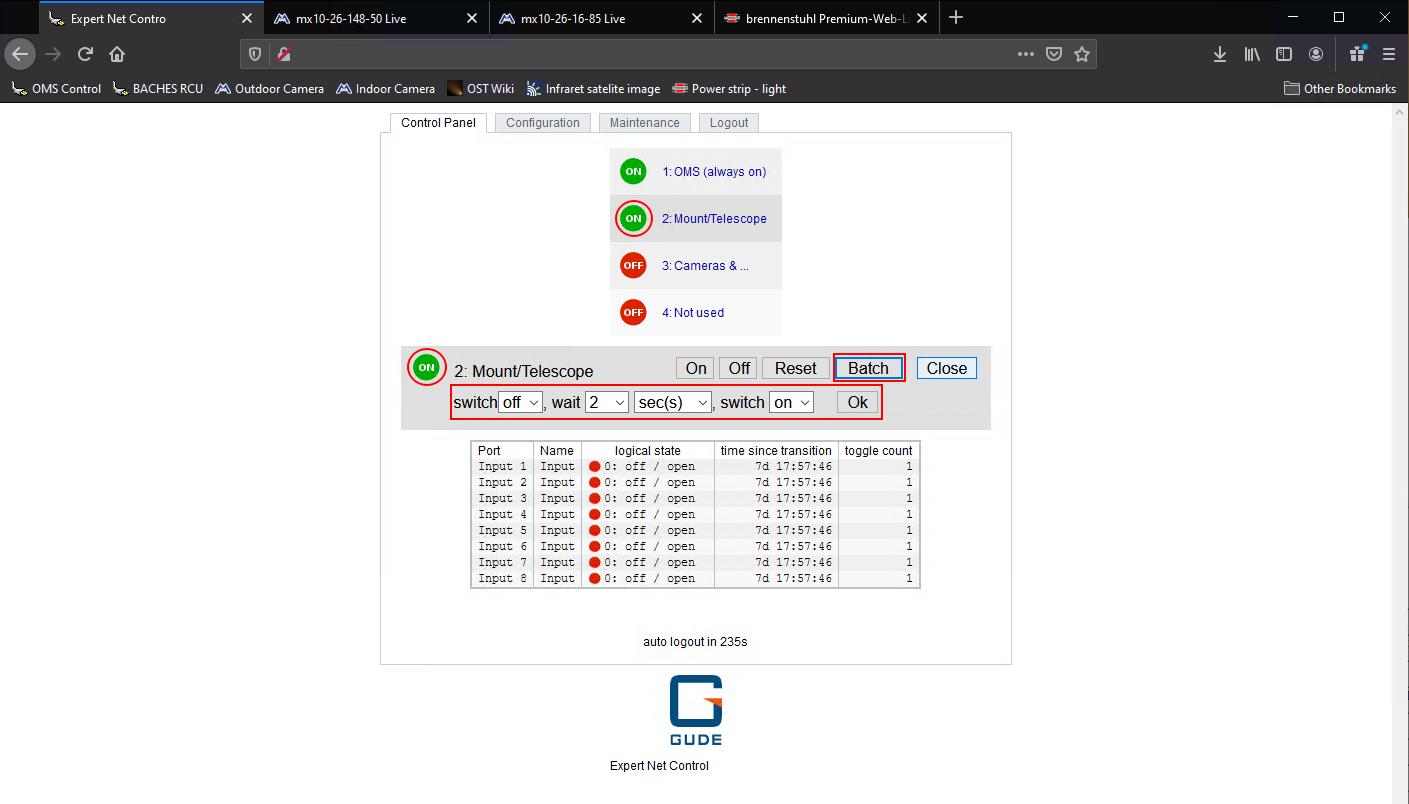
- Shut down telescope/mount: In the same tab of the web browser, first click on the Mount/Telescope item. After that, the following two steps have to be executed:
- click on the Batch button and then make sure that the settings are as follows: switch
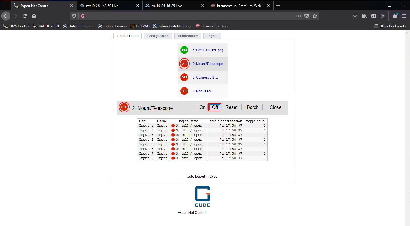
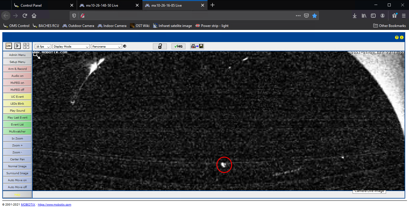
off, wait3sec(s), switchon(see photo above). Then click on Ok. The status indicator will briefly go to red and then change back to green. This is perfectly normal and expected. - Wait at least 20 seconds for the mount to shut down. You can look at the internal webcam to check. When parked, the mount's indicator light is in the center of the camera's field of view (see photo below). If the indicator light is off, the mount has successfully shut down. You can then click Off. The status indicator will then change back to red and remain so.
- Close web browser]
- Log out user
Problems and their solution
A compilation of problem solutions to known error sources can be found in our article Known error sources and their solution.
