Table of Contents
Telescope setup and maintenance
Setup of the GM4000 HPS II mount
Using the mount directly via the handheld terminal
Alignment
The accuracy of the tracking can be improved with a good alignment. This procedure can gather information on possible errors in the azimuth and pole-height settings (correction suggestions for the hardware), to reduce errors in the alignment of the pole axis.
Alignment with 2 stars
MENU - Alignment - 2-Stars - ENTER
- select one star from the presented list and press ENTER
- select the second star from that list (it should have a large distance to the first in RA/DEC) and press ENTER
- the telescope changes its position and points to the first star
- the star should be in the center of the eyepiece, adjust the pointing with the N - S - E - W buttons as needed (use the eyepiece with the cross hair to easily estimate the center)
- once the star is centered, confirm with ENTER
- repeat the previous two steps with the second star
If the alignment has been successful, the hand terminal will show
Alignment complete
Refining the alignment
It is advisable to refine the alignment with further stars. Select this option in the hand terminal
MENU - Alignment - Refine 2-Stars - ENTER
- as before, the hand terminal will display a list of stars
- select one star to which the telescope will move
- center the star in the eyepiece and confirm with ENTER
- the hand terminal will then show:
Alignment refined
- repeat this procedure until an alignment with 10 stars has been completed
- to improve the accuracy all stars should be spread across the whole sky
There are further methods to change/improve the alignment that are documented in the manual of the GM 4000 HPS II, which can be found in room 2.009.
Saving, restoring, and deleting of an alignment
Once a good alignment has been reached, it is recommend to save it:
MENU - Alignment - Align Database - Save Model
The telescope will then swing to the so called “Home Search” position and saves the alignment. This alignment can then be restored after an alignment loss with:
MENU - Alignment - Align Database - Load Model
The telescope will then once again swing to the “Home Search” position and load the previously saved data.
It can be necessary to delete a (bad) alignment, e.g. if it only proves to be useless after it has been saved. An alignment can be deleted with:
MENU - Alignment - Align Database - Delete Model
Alternatively one can reset the mount:
MENU - Alignment - Reset at Home
In doing so, the alignment will be deleted and the mount restored to the factory settings. Only use this option with caution!
Alignment Information
Information on the current alignment can be found at:
MENU - Alignment - Align info
With this option, the mount among others gives information on how the orientation of the pole axis can be improved. The terminal will display something like:
 To center pol ax
 move .07 Rt 0.05 Up
Using the OMS
Creating a pointing model
The advantage of setting up the mount via the OMS is that a much more precise pointing model can be created, since not only a few stars are used, but up to 100 star fields distributed over the whole sky can be utilized. The exact position of these star fields is determined automatically with the help of the so-called Plate Solving. We use the software ModelCreator.
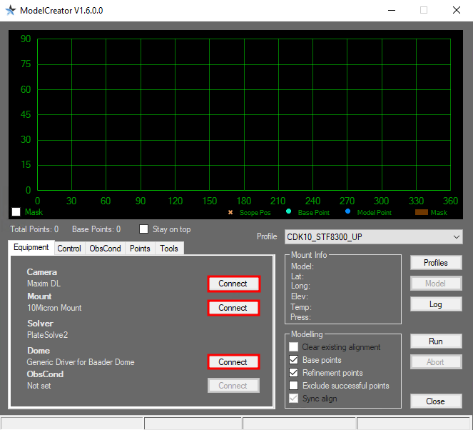
The most important settings in the Equipment tab such as Camera, Mount, Solver, and Dome should already be preset. These settings are stored as profiles. The predefined profiles can be selected from the Profile drop-down menu. By clicking on Profiles the profiles can be edited and also new ones can be created. By clicking on the Connect buttons at Camera, Mount, and Dome the corresponding devices can be connected to the ModelCreator. In the case of the camera, it must be ensured that the camera is connected beforehand to MaxIm DL because ModelCreator fetches the data from there.
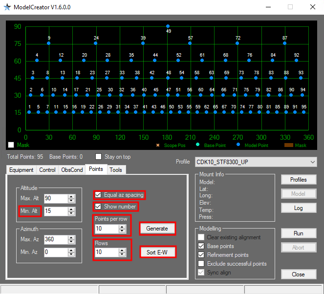
Next you should set the points where ModelCreator will create images of the sky. You should set a minimum height above the horizon (Min Alt), because points too close to the horizon do not make sense due to the long way the light travels through the atmosphere. It has been proven that at least a minimum altitude of 15° is necessary. Furthermore, it has turned out to be useful to activate the option Equal az spacing in order to achieve an optimized distribution of the points. If you also activate the option Show number, the order in which the points are processed will also displayed. Afterwards you can click on Generate to generate the points. After that you can click on Sort-EW to sort the points from east to west. This significantly reduces the overall slewing time required by the mount. For our final pointing model we usually use up to 100 points. For this we usually set Points per row and Rows to 10 each. Additionally 3 base points can be selected. Click on the corresponding points with the mouse.
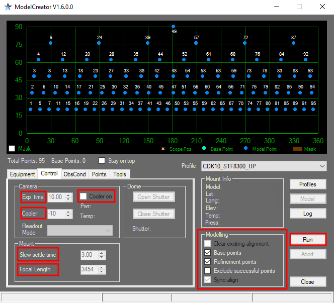
It has proven useful to increase the exposure time for points close to the horizon, because there the air mass increases significantly. Otherwise not enough objects can be identified. For points in the Milky Way, on the other hand, it can happen that no solution can be achieved by plate solving, because there seem to be too many stars in this area. In this case, it might be helpful to reduce the exposure time. The exposure time can be adjusted via the Control tab. Here you should also set a Slew settle time of 3s and the focal length of the telescope (Focal Length).
Afterwards the calibration can be started by clicking Run. Before that, make sure that the options Clear exsisting alignment and Sync align are activated. Then ModelCreator moves the mount to the first point, takes an image, starts PlateSolve, searches for the exact coordinates of the star field, uses this solution to improve the pointing model and continues with the next point.
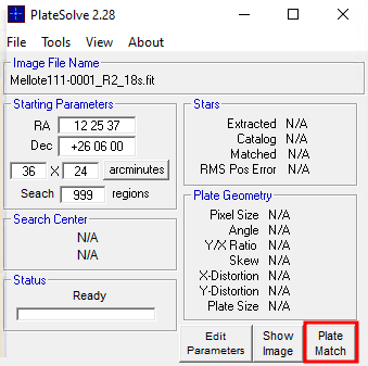
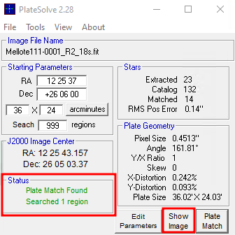
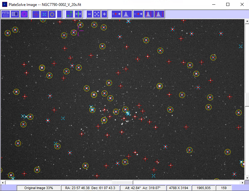
PlateSolve identifies the stars in the respective star field and compares their position with star catalogs. Starting from the coordinates provided by the telescope, a spiral outward search is performed. In the example above (the screenshot in the middle), the first step of the iteration was already successful and the star field was successfully identified. If the pointing model is not yet as good as in this example, which is usually the case when a completely new pointing model is created, it may take several iterations until the star field is identified. If after 99 iterations the star field has not been found, the iteration is aborted and ModelCreator moves on to the next pointing.
Analyzing a pointing model
Will follow soon…
A-PEC
The Periodic Error Correction (PEC) can help to improve the tracking accuracy of the mounting by accounting for periodic errors of the worm gear. This error usually has a period of approx. 3 min 20 sec (3.3 minutes), while the PEC can correct for shorter periods, too. The error of the worm gear is usually irrelevant as long as the observations are only carried out with an eyepiece – in case longer observations are taken with CCDs, the corrections of this error are getting important.
The PEC has to be calibrated before it can operate properly. For this purpose, the mount needs detailed information on the deviations from the ideal tracking behavior. One possibility to achieve this is by centering a bright star in an eyepiece and following its motions with the hand terminal (the N - S - E - W buttons) for a while. A more sophisticated option is based on the autoguide functionality of our CCD cameras, as the precision is higher this way. It is recommended to train the PEC directly via the handheld terminal. The training algorithm of the PEC is started by means of:
Drive -> A-PEC control -> A-PEC Training
In the next step choose the time period during which the PEC shall be “trained”: 15, 30, or 60 minutes. The longer the training is, the better is the result of the PEC. After the training has been completed the corrections are calculated and the PEC is automatically activated.
Pole height adjustment
- will follow…
Schmidt-Cassegrain telescopes (C14, C11, & C8)
Check and improve the collimation
Check
- the telescope should have ambient temperature
- drive to a bright star in zenith (Polaris can be used, too)
- use the 25mm ocular (or the webcam)
- defocus the star so it takes about one sixth of the FoV (field of view) and gets a doughnut shape
- if the shadow of the secondary mirror (the inner part of the doughnut/defoussed star) is off-centered, the collimation of the telescope is erroneous
Improvement
- move the star (using the N - E - S - W buttons) in the direction to which the shadow is off-centered until the edge of the FoV is reached
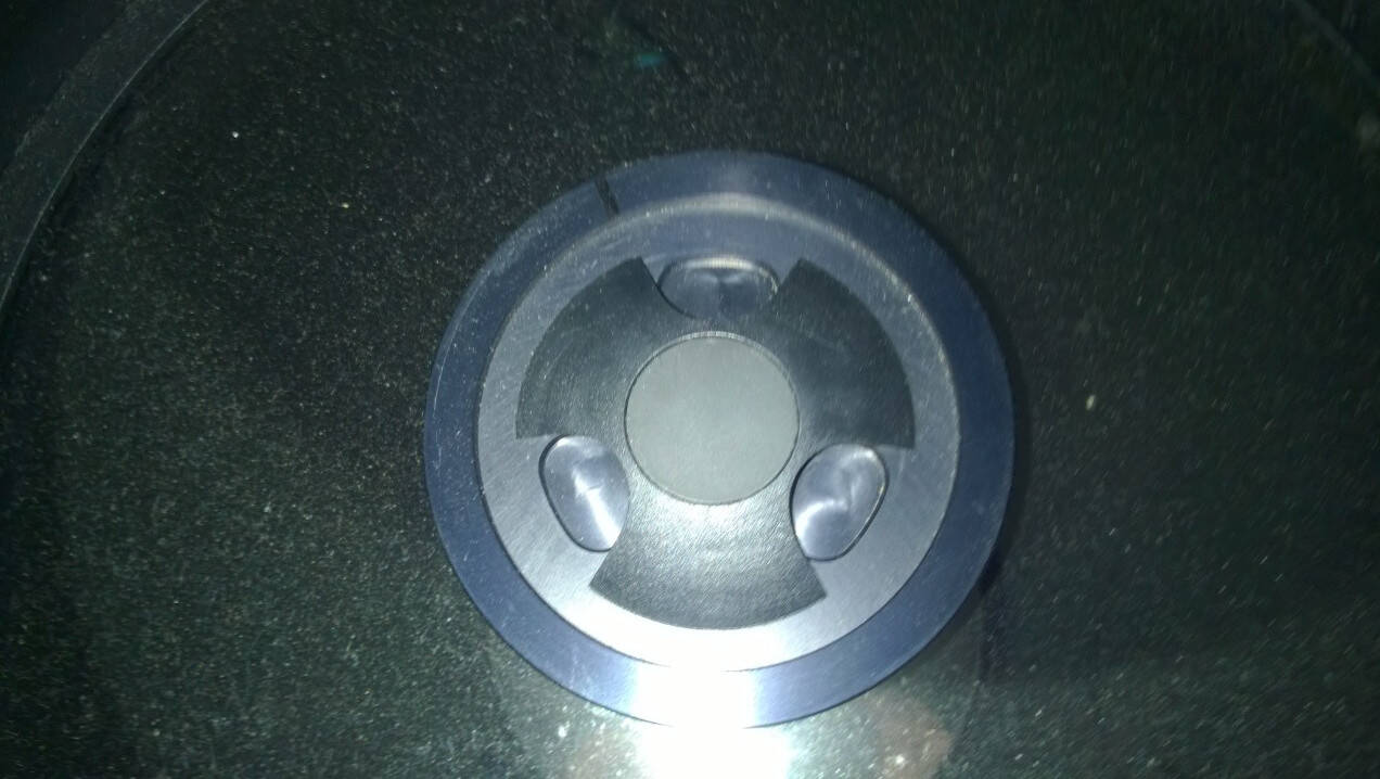
- turn the three screws on the backside of the secondary mirror (see Figure below) until the star is again in the center of the FoV. To achieve that:
- tighten the screw(s) in the direction of the offset
- loosen the other(s)
- repeat this procedure until the shadow is centered on the defocused star
- repeat with eyepieces of higher magnification (note: in 6mm eyepieces the star is kept focused and the correction is carried out in relation to a (very) thin diffraction ring)
ATTENTION: ONLY VERY MARGINAL CORRECTIONS NEED TO BE APPLIED TO THE SCREWS!
Maintaining the Schmidt plate
Do not touch and always put the lid on the telescope after observations to avoid unnecessary dust accumulation on the Schmidt plate! Especially in autumn and winter it is advisable to use the dew cap to prevent unnecessary condensation.
Cleaning
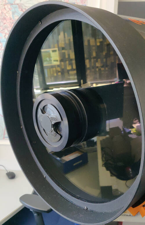
From time to time the Schmidt plates of our Schmidt-Cassegrain telescopes have to be cleaned. This is a difficult process, because we have to avoid at all costs that the Schmidt plate is damaged e.g. by scratches.
The following materials are required:
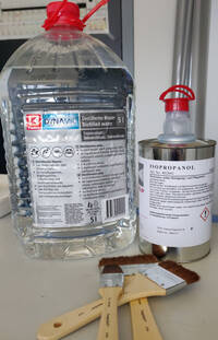
- Distilled water
- Alcohol - isopropanol
- Cosmetic wipes or soft cellulose handkerchiefs that can be separated into the individual layers.
- Very important: The tissues must not contain lotions, odorants, or anything else along these lines
- Cotton balls
- Camel hair brush
- Microfiber cloth
- Pure dishwashing detergent with no other additives such as hand conditioners
- Optional: A small bellows or a compressed air bottle without propellant
Procedure:
- The first thing to do is to put the telescope in a position where it looks a little bit towards the ground (if possible). In this way, cleaning fluid can be prevented from running into the telescope.
- Loose dust can be removed using the bellows or the compressed air bottle. Care must be taken to blow at as shallow an angle as possible onto the Schmidt plate to blow the dirt off the Schmidt plate and not push it further onto the Schmidt plate. With a compressed air bottle, do test sprays first so you can get a feel for how much air is coming out. In addition, this is a good way to make sure that the use of the compressed air bottle does not cause any additional deposits to form on the Schmidt plate.
- Next, further impurities can be removed using the camel hair brush.
- A mixture of distilled water and isopropanol in a ratio of 50:50 or 50:60 is suitable as a cleaning fluid. Furthermore, for heavily soiled surfaces, a little washing-up liquid can also be added. No more than 1 drop should be added per 500 ml of cleaning liquid, otherwise residues may remain on the Schmidt plate.
- If the Schmidt plate is heavily coated with sticky pollen, it is advisable to soak the deposit carefully. To do this, carefully apply a little cleaning liquid with a brush. Work in squares if possible.
- Then remove the heavy soiling with moistened cotton balls. Always work in straight lines, preferably from the inside to the outside, rotating the cotton ball so that the dirt adhering to the cotton ball does not rub over the surface. Use very little pressure and never rub in circles.
- Then remove the remaining impurities with moistened cosmetic tissues. For this purpose, again stroke in straight lines from the inside to the outside with light pressure, avoiding that the absorbed dirt rubs against the Schmidt plate.
- The cleaning liquid should dry off without leaving any residue. If this is not the case, the cleaning process should be repeated again with a newly prepared cleaning solution without detergent.
Corrected Dall-Kirkham telescope - CDK20
Collimation
- Will follow soon …
Cleaning the mirror
To clean the mirror, basically the same steps must be followed as for cleaning the Schmidt plates on Schmidt-Cassegrain telescopes with the following exceptions:
Additional materials needed:
- Paper towels
Changes in procedure:
- When cleaning the primary mirror:
- In addition, some paper towels should be placed in the carbon fiber sleeve around the mirror so that excess cleaning fluid is absorbed by them and does not run behind the mirror and come in contact with the electronics installed there. The paper towels must not come into contact with the mirror.
- When cleaning the secondary mirror:
- The telescope should look a few degrees above the horizon in this case.
Problems and their solution
We also have a compilation of problem solutions to known error sources.
