Table of Contents
Maxim DL
Please note that this article is currently being updated.
Maxim DL is currently the primary interface used to control the observatory, operate the cameras, and perform observations.
Interface and Basic Operation
Maxim DL can be started most easily by double-clicking the Maxim DL 6 icon on the desktop or via the taskbar.
Main Window
In the image on the left (or below), which shows the main window of Maxim DL, the most important buttons are highlighted. The red button opens the Observatory Panel, which contains the controls for the dome and the telescope. The green button opens the Camera Control Panel, which provides access to the camera controls. These two windows are described in detail below.
The blue, pink, and brown buttons provide access to image information and display options. The header information can be opened via the brown button. The blue button allows, for example, inspection of the counts in individual pixels or within a selected aperture. The pink button provides access to basic image scaling controls.
Observatory Panel
The Observatory control window contains different tabs used to control the various components of the observatory. Objects can be selected by entering their coordinates, choosing them from a catalog, or marking them on the All-Sky map. The dome can be opened, closed, and manually repositioned if necessary. Furthermore, the telescope can be moved manually via this control window and parked again after the observations are completed.
Setup Tab
The Setup tab is used to establish the connection to the telescope, the dome, and the focuser. Click the respective Connect button next to each entry or use Connect All to establish connections to all components simultaneously. Other entries such as Rotator are not relevant for our setup.
To disconnect the devices after the observations, use the individual Disconnect buttons or Disconnect All.
When planning an automatic or semi-automatic observation night, you can also activate the automatic shutdown mechanism as an alternative. To do this, click on the Auto Shutdown button at the bottom of the Setup tab. The Active Shutdown Triggers section in the window that opens (see below) lists the various triggers that can cause an automatic shutdown. In the example below, these are:
Twilight, which is set toAstro. This means that the trigger is activated as soon as astronomical twilight begins.Sequence Ended, which activates once the current sequence has finished.Target near horizon, which is set toWithin 30°. The trigger is activated when the altitude of the object above the horizon falls below 30°.
The Active Shutdown Commands section lists the actions that occur once the shutdown has been triggered. In our example, the dome closes (Close dome shutter), the telescope parks (Park scope) and the camera coolers switch off (Warm up camera coolers).
All of these options can be configured using the Configure button. Once all the settings have been configured, auto shutdown can be activated using the Arm button.
Dome Tab
The Open and Close buttons are used to fully open or close the dome. The dome slit and hatch always move into their fully open or fully closed positions.
Ensure that Slave Dome To Scope is activated; otherwise, the dome will not follow the telescope. This option is automatically deactivated each time the dome is opened or closed, or when the telescope is parked, and must therefore be reactivated if required.
The dome can be moved manually via the functions in the Position section. This is particularly useful when the telescope and dome slit are not aligned correctly and need to be recalibrated, as shown in the example above.
Telescope Tab
The upper-left section of the Telescope tab shows the current pointing position and status of the telescope. Right ascension and declination are displayed for the current date as well as for the standard epoch J2000. In addition, altitude above the horizon and azimuth are shown. In the example below, the telescope is tracking and otherwise idle.
The buttons in the Nudge section allow manual movement of the telescope. The step size can be selected via the drop-down menus. Each movement can be aborted using the Abort button.
In the Target Coordinates section, right ascension and declination can be entered manually and the telescope can be slewed to the selected object using Go To. The Zoom To button switches to the Zoom tab, which displays a sky map centered on the respective coordinates.
The Park button in the Mount section parks the telescope after the observations.
Catalog Tab
Using the Catalog tab, the built-in catalogs can be searched for objects. First, select a category from the Category drop-down menu: Stars, Deep Space, or Solar System. Under Object ID, either select the object directly or choose a catalog and enter the catalog number (or part of it). After clicking Search, a list of possible matches is displayed. Select the desired object and click Go To to slew to it.
Zoom Tab
In the Zoom tab, the sky map around the selected object is displayed. Via the options button (arrow) on the right and the context menu, various settings such as zoom level can be accessed.
Right-clicking on any point in the map allows you to slew the telescope to that position via Slew to Mouse Position. If you right-click on an object, it can be selected directly (e.g., Slew to 119 Tau).
All Sky Tab
The All Sky tab shows the current sky. By right-clicking, you can zoom into any area; this automatically switches to the Zoom tab. The options button (arrow) on the right provides access to additional settings.
Camera Panel
The Camera Control window is used to operate the cameras and acquire images.
Setup Tab
As the name suggests, this tab is used to connect the cameras to Maxim DL. The procedure differs slightly depending on the manufacturer. Here, the setup for QHYCCD cameras is described, as these are the cameras primarily used.
For each camera model, the appropriate driver must be selected. This applies both to the main camera and to the filter wheel. If a guiding camera is used, it must also be connected here. Typically, the main camera is connected as Camera 1, while the guiding camera is connected as Camera 2.
The first step, regardless of the manufacturer, is to click on Setup Camera.
Connecting QHYCCD Cameras:
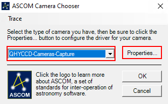
In the window that opens, select ASCOM from the Camera Model drop-down menu and then click Advanced… (Step 1). A second window will open. In this window, select QHYCCD-Cameras-Capture from the drop-down menu and click Properties… (Step 2). This opens the settings menu for the ASCOM driver for the QHYCCD cameras. ASCOM serves as the standardized interface through which many of the observatory’s hardware components are controlled.
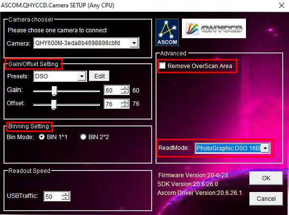
In the final step (3), all relevant settings for the ASCOM driver can be configured. These include the readout mode, selectable via the ReadMode drop-down menu. Available options include PhotoGraphic DSO 16bit, High Gain Mode 16bit, Extend Fullwell Mode, and Extend Fullwell 2CMS. Under Gain/Offset Setting, the Gain and Offset can be adjusted. These settings can be saved as Presets. For our use case, the Remove Overscan Area option should also be activated. After configuration, close all three windows by clicking OK.
Connecting QHYCCD Filter Wheels:
To connect a filter wheel, first click on Setup Filter.
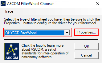
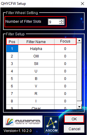
In the first step, select ASCOM from the Filter or Controlling Camera Model drop-down menu and click Advanced…. In the next window, select QHYCCD FilterWheel and click Properties… (Step 2). A driver settings window will open. These settings usually only need to be configured once. Select the Number of Filter Slots (in our case 9), define the filter names, and enter any required focus offsets (Step 3). Confirm and close all windows by clicking OK.
Final Step:
Click Connect. Under Coolers, activate the cooling system and set the target temperature under Cooler.
Expose Tab
This tab contains the most important settings for image acquisition. Predefined configuration sets can be selected under Exposure Preset, and new presets can also be created.
The most important parameter is the exposure time (Seconds). To the right, the status line indicates the current camera activity. In the example shown below, the camera is idle.
The selected filters are displayed under Filter Wheel. Binning options are accessible via the X Binning and Y Binning drop-down menus. In some cases, it is also possible to select the Readout Mode.
The basic operating modes are:
- Single – one exposure
- Continuous – consecutive exposures displayed sequentially (suitable for focusing)
- Autosave – automated exposure series
In Continuous mode, images are taken and displayed one after another using the defined exposure time. Further details on the lower three panels can be found in the focusing instructions. Additional options are available via the Options button (arrow).
Guide Tab
The Guide tab contains the primary settings required for telescope guiding. Detailed instructions are provided in the corresponding guiding how-to.
Screen Stretch Panel
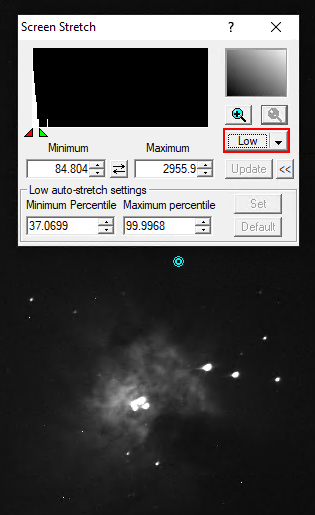
The Screen Stretch Panel allows adjustment of the image display scaling. These settings affect only the visualization of the image and do not modify the underlying data.
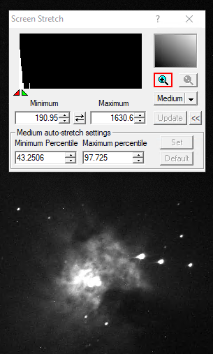
In the first example below (showing M42), the scaling is set to Low. Increasing the scaling to Medium reveals significantly more detail. Additional predefined scaling options are available from the drop-down menu.
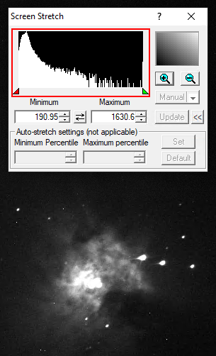
Clicking the plus symbol in the upper right section zooms into the histogram displayed in the upper left. This allows fine adjustment of the scaling using the red and green triangles, where the red triangle defines the black level and the green triangle defines the white level. The same adjustment can be performed using the Minimum and Maximum fields.
Information Panel
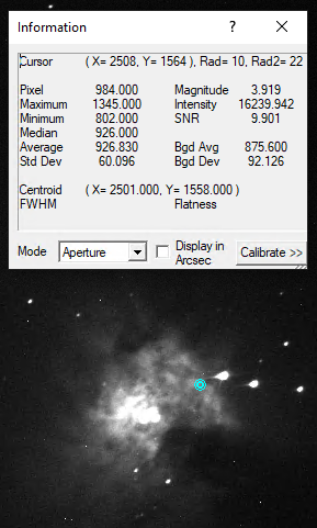
The Information Panel is particularly useful for checking whether an image is overexposed and identifying which stars may be saturated.
Of particular interest are the Pixel and Maximum values. In the default Aperture mode, the information is derived from the cyan aperture shown on the image, which can be moved, for example, onto a bright star.
When evaluating stellar image quality, the signal-to-noise ratio (SNR) and the full-width at half-maximum (FWHM) are also relevant parameters. For our predominantly uncalibrated images, values such as Magnitude are generally not meaningful.


